The charging system consists of
an
alternator with
an
internal
voltage
regulator,
an
engine-mounted circuit
breaker,
a battery and connecting wires.
Because
of the use of IC's (integrated circuits), the
eleCtronic
voltage
regulator
is very compact
and
is built
into
the
rear
bracket of the alternator.
Charging
Voltage
Test
If you suspect that the alternator is not producing
enough
voltage to
charge
the engine's battery,
perform
the following voltage test.
ANPHETER
r-
__________
~e{A
e
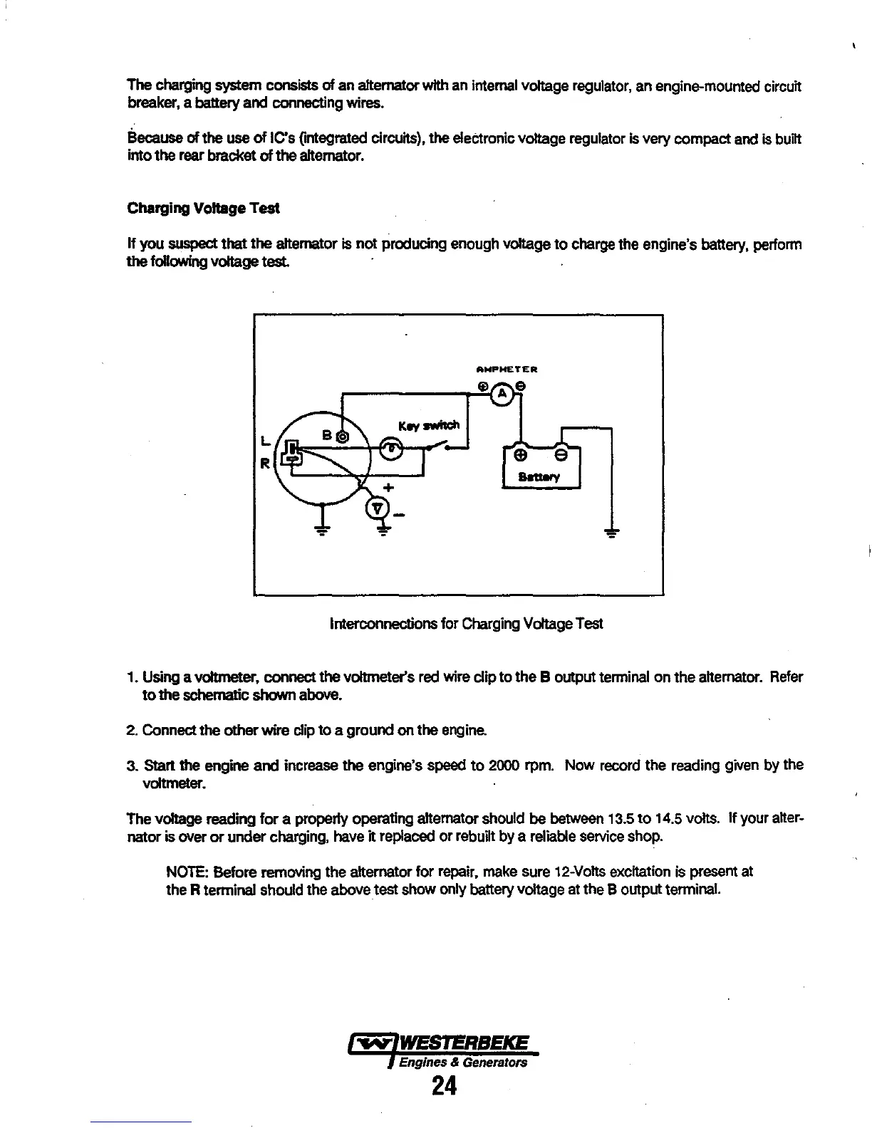
Interconnections for
Charging
Voltage
Test
1.
Using
a voltmeter, connect the voltmeter's
red
wire
dip
to the B output
terminal
on the
alternator.
Refer
to
the
schematic
shown
above.
2.
Connect the other wire dip to a ground
on
the
engine.
3. Stan the engine and increase the engine's
speed
to
2000
rpm. Now
record
the reading
given
by
the
voltmeter.
The voltage reading for a properly operating alternator
should
be
between
13.5
to
14.5
volts. If your
alter-
nator is
over
or
under charging,
have
it replaced or rebuilt by a
reliable
service
shop.
NOTE:
Before removing the alternator for
repair,
rnake
sure
12-Volts
excitation
is
present
at
the R terminal should the above test show only battery voltage
at
the B output terminal.
Engines & Generators
24