VALVE CLEARANCE ADJUSTMENT
Valve Clearance Adjustment
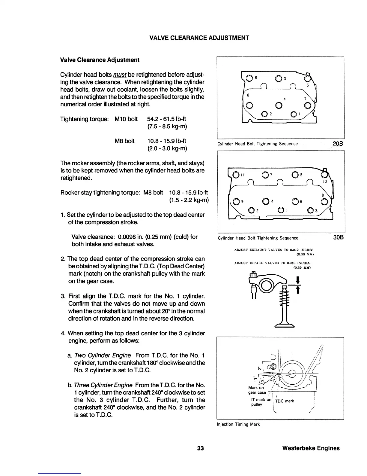
Cylinder
head
bolts
lIl.USt.
be
retightened before adjust-
ing
the
valve
clearance.
When
retightening the cylinder
head
bolts, draw out coolant, loosen the bolts slightly,
and
then
retighten the bolts to the specified torque
in
the
numerical order illustrated at
right.
Tightening torque: M
10
bolt
54.2
-
61.5
Ib-ft
(7.5
-
8.5
kg-m)
M8
bolt
10.8
-
15.9
Ib-ft
(2.0
-
3.0
kg-m)
The
rocker assembly
(the
rocker
arms,
shaft,
and
stays)
is
to
be
kept
removed
when
the cylinder
head
bolts
are
retightened.
Rocker
stay tightening torque:
M8
bolt
10.8
-
15.9
Ib-ft
(1.5
-
2.2
kg-m)
1.
Set
the cylinder to
be
adjusted to the top
dead
center
of the compression
stroke.
Valve
clearance:
0.0098
in.
(0.25
mm)
(cold) for
both intake
and
exhaust
valves.
2.
The
top
dead
center of the compression stroke
can
be
obtained by aligning the
T.O.C.
(Top
Oead
Center)
mark (notch)
on
the crankshaft pulley with
the
mark
on
the gear
case.
3.
First align the
T.O.C.
mark for the
No.
1 cylinder.
Confirm that the
valves
do not
move
up
and
down
when
the crankshaft
is
turned about
20°
in
the
normal
direction of rotation
and
in
the
reverse
direction.
4.
When
setting the top
dead
center for
the
3 cylinder
engine,
perform
as
follows:
a.
Two
Cylinder
Engine
From
T.O.C.
for the
NO.1
cylinder, turn the crankshaft
180°
clockwise
and
the
NO.2 cylinder
is
set
to
T.O.C.
b.
Three
Cylinder
Engine
From
the
T.O.C.
for the
No.
1 cylinder, turn the crankshaft
240°
clockwise to
set
the
No.3
cylinder T.O.C. Further, turn the
crankshaft
240°
clockwise,
and
the
No.
2 cylinder
is
set
to
T.O.C.
33
4
o
0
2
0
1
Cylinder
Head
Bolt Tightening Sequence
Cylinder
Head
Bolt Tightening Sequence
ADJUST
EXH.\USl'
V.UVES
TO
0.012
INCH&'!
(11.:111
~
..
)
ADJUST
INTAKE
VALVES
TO
0.010
I:SCHES
(0.2~
MM)
Injection Timing Mark
208
308
Westerbeke Engines
 Loading...


