Piston
and
Connecting
Rod
Removal
1.
Remove the cylinder head assembly.
2.
Remove the oil pan.
3.
Remove the oil screen.
4.
Chalk the cylinder number on the side face of the big end of each connecting rod
to
prevent confusion
of
connecting rods.
5.
Remove the connecting rod cap from each piston
and rod
assembly and draw the assembly upward
from the cylinder. Take care not
to
allow the con-
necting rod
to
scratch the crankshaft pin and
cylinder. Keep the removed parts (connecting rod,
rod cap, piston etc.)
classified
by
cylinders.
6.
Remove the rings from each piston with the piston
ring
pliers.
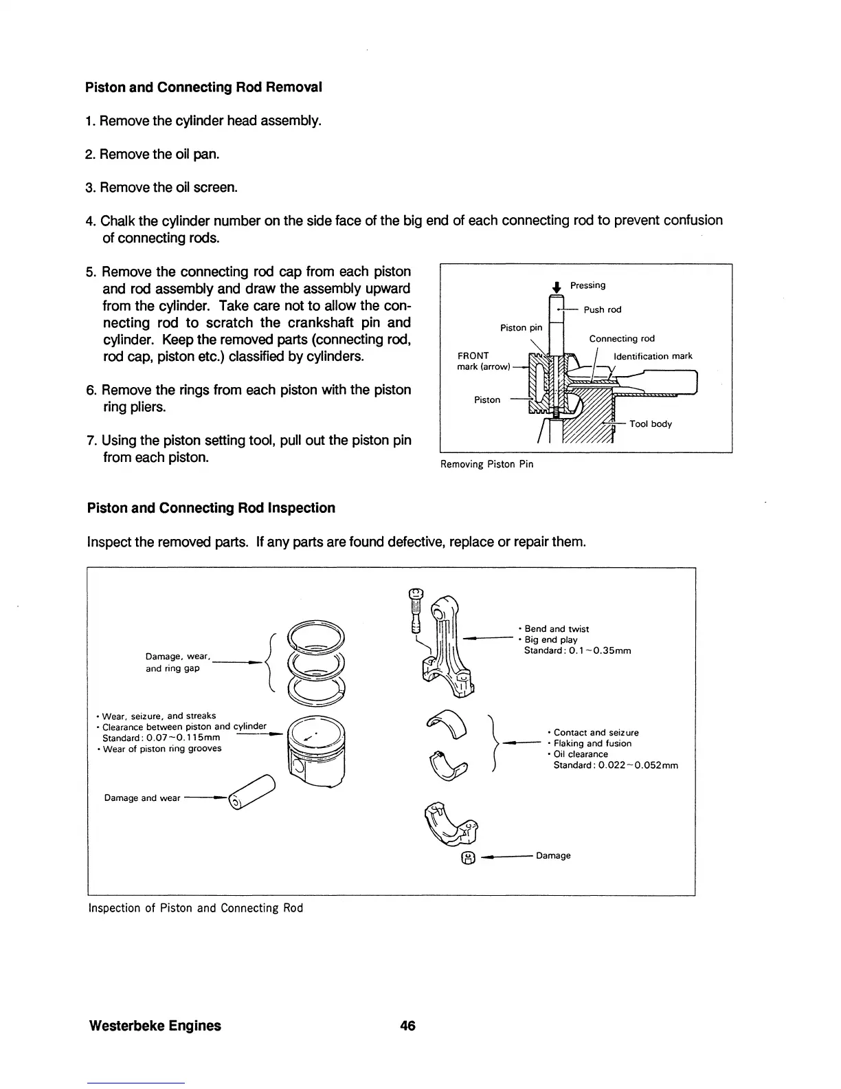
7.
Using the piston setting tool, pull out the piston pin
from each piston.
Piston
and
Connecting
Rod
Inspection
FRONT
mark (arrow)
Piston
Removing Piston Pin
Pressing
Inspect the removed parts. If any parts are found defective, replace
or
repair them.
Damage, wear,
__
{
08----::
and ring gap
~
~~
• Wear, seIzure, and streaks 8
• Clearance between piston and cylinder
tf~.
~
Standard:O.07-0.115mm
-----
~
• Wear of p,ston ring grooves
~
$
Damage
and wear
-------V
Inspection of Piston and Connecting
Rod
Westerbeke
Engines
46
• Bend and twist
---
• Big end play
Standard: 0.1
-O.35mm
}
•
Contact and seizure
-
• Flaking and fusion
• Oil clearance
Standard:
O.022-0.052mm
®
___
--
Damage
 Loading...


