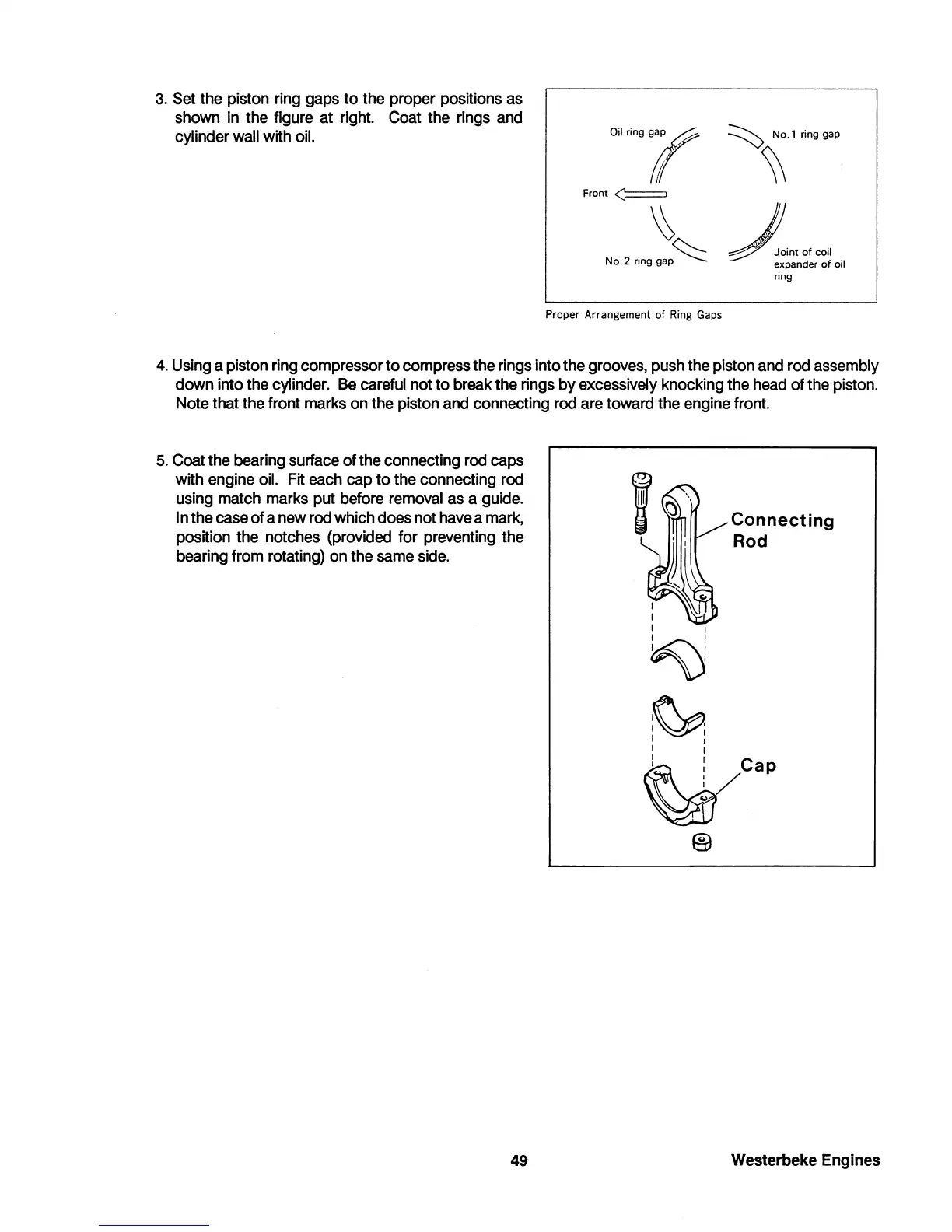
3.
Set the piston ring gaps
to
the proper positions as
shown in the figure at right.
Coat the rings and
cylinder
wall with oil.
Ol'ri"if
Front
~
~
No.2
ring
gap~
Proper Arrangement of Ring
Gaps
~
No.1 ring gap
~
,J!."
0'
0011
expander
of
oil
ring
4. Using a piston ring compressor
to
compress the rings into the grooves, push the piston and rod assembly
down into the cylinder. Be careful not
to
break the rings
by
excessively knocking the head of the piston.
Note that the front marks on the piston and connecting rod are toward the engine front.
5.
Coat the bearing surface
of
the connecting rod caps
with engine oil. Fit each cap
to
the connecting rod
using match marks put before removal as a guide.
I n the case
of
a new rod which does not have a mark,
position the notches (provided for preventing the
bearing from rotating) on the same side.
49
I
I
~
:
:
I I
I
~
I I
I I
Connecting
Rod
~cap
®
Westerbeke Engines
 Loading...


