5. Wiring Instructions
a. Smart Power Unit Wiring Instructions
Refer to the below table for wiring specification, use copper conductors only. All
wiring shall meet local codes/standards and be performed by qualified personnel.
Terminal Name
Recommended
Wire Gauge
Wire Temperature
Rating
Remark
BATT+
10 AWG
Min. 75
Tightening wire with 25 in-lbs torque
BATT-
10 AWG
Min. 75
Tightening wire with 25 in-lbs torque
Slide 1~Slide 3
10 AWG
Min. 75
The wire end needs to employ UL Listed 250 female
quick disconnect
Water Pump
14 AWG
Min. 75
Push-in connection
Awning 1~Awning 2
14 AWG
Min. 75
Push-in connection
Light 1~ Light 4
22 AWG
Min. 75
Push-in connection
WH-Gas, WH-Elec
22 AWG
Min. 75
Push-in connection
Tank Levels, Brake
Light, WH-DSI
20 AWG
Min. 75
Push-in connection
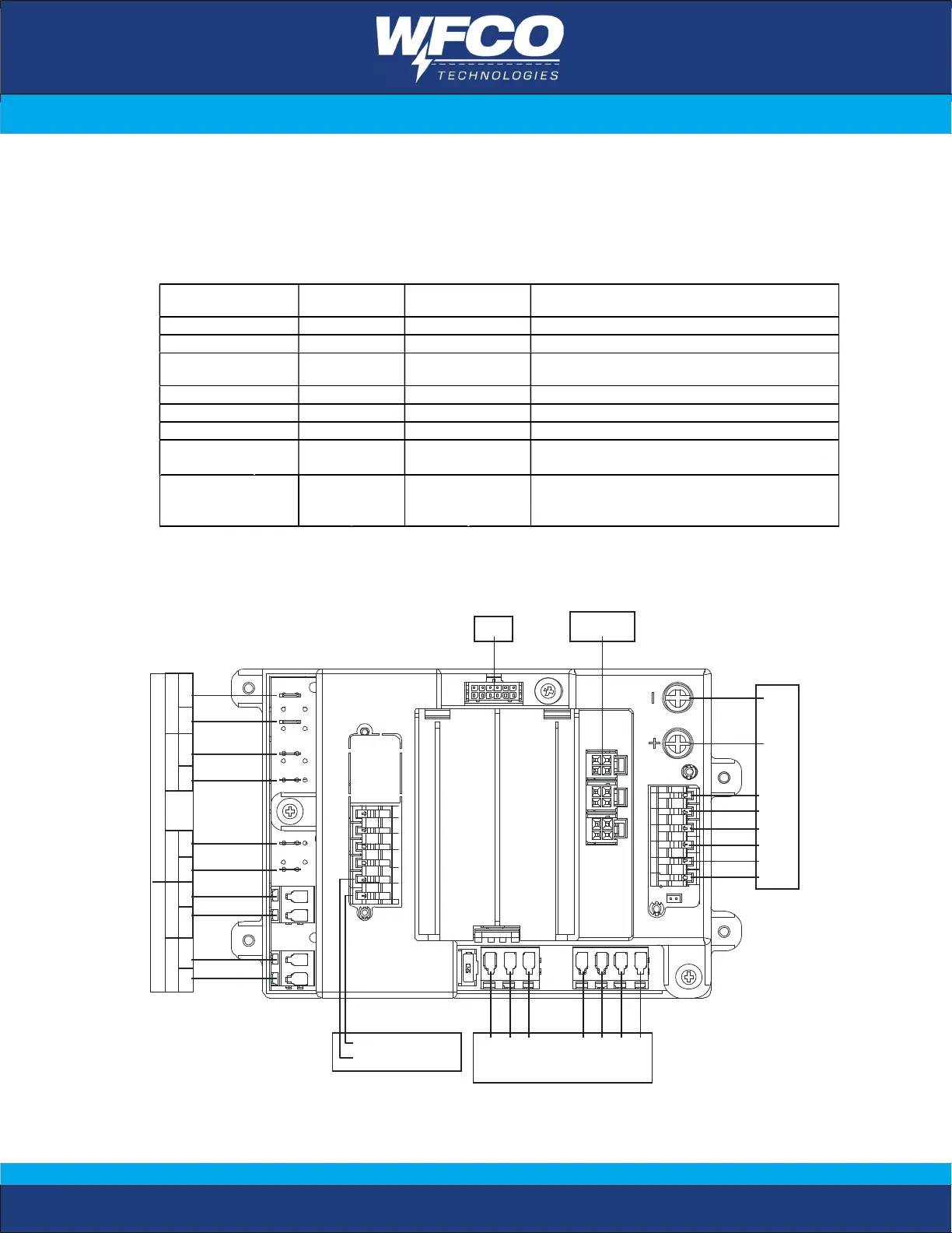
b. Smart Power Unit Wiring Diagram
Light 4
Light 3
Light 2
Light 1
3 0A15A
Slide1Slide2
WH- Gas
WH-E le s
P ump
Wat er
WH-DSI
Brake Light /LockOut
BATT-
BATT+
Black
Gray
Gray
Black
Gray
Fresh
ExtR etE xtR etE xtRetExtRetExtRet
Slide3Awning1Awning2
WF3510-A
MORS