AC System Wiring
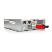
e AC Pass-rough and AC output wiring location is on the lower le side of the rear
panel. Both input and output connections should be made at the same time. Connections to
the WF-5118 Inverter should be made using 12 AWG Romex wire. Connections to the WF-
5120 Inverter must be made using 10 AWG Romex wire.
Begin cable installation by backing out the knurled screw on the wiring inspection panel.
Remove and set aside the screws that hold the AC input and AC output cable connectors in
place. Remove the clamp plates. Open the clamps by backing out the clamp screws to widen
the opening.
Making AC Input (Pass-rough) Connections on the WF-5118 Inverter
1. Insert approximately 4” of one end of a 12 AWG Romex wire through the clamp on the
AC input plate and tighten the clamp screws to secure the cable. e other end of this
cable attaches to a circuit breaker in the power panel.
2. Remove approximately 3 ½” of outer sheathing from the wire.
3. Separate the wires and strip ¾” of insulation from the White and Black wires.
4. Locate the AC input wires inside the WF-5118 Inverter wiring box. Connect the Romex
wires to the inverter output wires using listed wiring connectors. Wire Black to Black,
White to White, and Ground to Green. Make sure connections are secure.
5. Fold the connected wires back into the wiring box.
6. Reattach the clamp plate to the inverter and secure with the screw.
Making AC Output Connections on the WF-5118 Inverter
1. Insert approximately 4” of one end of a 12 AWG Romex wire through the clamp on the
AC output plate and tighten the clamp screws to secure the cable. e opposite end of
this cable attaches to the load circuit.
2. Remove approximately 3 ½” of outer sheathing from the wire.
3. Separate the wires and strip ¾” of insulation from the White and Black wires.
4. Locate the AC output wires inside the WF-5118 Inverter wiring box. Connect the Romex
wires to the inverter output wires using listed wiring connectors. Wire Black to Black,
White to White, and Ground to Green. Make sure connections are secure.
5. Fold the connected wires back into the wiring box.
6. Reattach the clamp plate to the inverter and secure with the screw.
Push all the wires back into the wiring box and fasten the inspection plate back in place with
the knurled screw.
Making AC Connections on the WF-5120 Inverter
To make AC input/output connections on the WF-5120 Inverter, follow steps 1 through 6
above, but use 10 AWG wire in place of the 12 AWG wire.
13
 Loading...