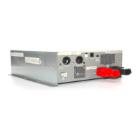
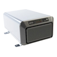
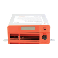
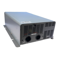
The WF-5300 Series Pure Sine Wave Inverter is a device designed to convert 12-volt battery power into 115-volt AC power, primarily for RV applications. It features an internal transfer switch that allows seamless switching between shore power or generator power and battery power. When an external AC source is available, the inverter enters a standby mode, ready to provide continuous AC power from the battery if the external source is interrupted. This ensures uninterrupted operation of connected appliances.
Important Technical Specifications:
The WF-5300 series offers two models: WF-5318 and WF-5320, with slight variations in their power output capabilities.
- Waveform: Both models produce a Pure Sine Wave output.
- Output Voltage: 115 V AC ±3%.
- Output Frequency: 60 Hz ±0.3 Hz.
- Output THD (resistive load): < 4%.
- Input Voltage Range: 10.0 - 16.0 V DC.
- Input Current (no load): < 1.6 amps.
- Peak Efficiency: > 90%.
Model Specifics:
| Feature |
WF-5318 |
WF-5320 |
| Continuous Output Power |
1800 W |
2000 W |
| Output Current |
15.7 A |
17.4 A |
| Surge Power (2 sec.) |
3600 W |
4000 W |
| Input Current (full load) |
180 A |
200 A |
| Rated Continuous Current |
180 A |
200 A |
| Minimum DC Wire Size |
2/0 |
2/0 |
| Maximum DC Fuse Size |
195 amps |
225 amps |
| Remote Control Panel Cable |
20 ft (6 m) |
30 ft (9 m) |
Transfer Switch Specifications:
- Transfer Time: < 20 ms.
- AC Pass-Through Rating: 24.8 amps.
- Switch to Shore Power: > 80 Vac or < 130 Vac.
- Switch to Inverter: < 90 Vac or > 140 Vac.
Protection Features:
Both models include robust protection systems to ensure safe and reliable operation:
- Output Circuit Breaker: 30 A.
- Overload Protection: Auto shutdown with auto recovery. The inverter will stop if too much current is drawn, and after 40 seconds, it will automatically attempt to restart. Users can also manually cycle the power to restart sooner.
- Short Circuit Protection: Auto shutdown if the AC output experiences a short circuit. The inverter can be restarted once the problem is corrected.
- Over Temperature Protection: Auto shutdown with one auto recovery during operation. If overheating persists, manual cycling of the power switch may be required.
- Battery Reverse Polarity Protection: No damage to the inverter if polarity is reversed; it simply will not operate until corrected.
- Under/Over Voltage at Input: The inverter will sound an alarm if battery input voltage drops below 11 volts and stop if it drops below 10 volts. Similarly, an alarm will sound if the input voltage exceeds 15 volts, and the inverter will stop if it goes above 16 volts. This protects both the inverter and the battery from damage.
- AC Circuit Breaker: A 30-amp auto-resettable circuit breaker protects the AC output circuit from excessive current, including during pass-through mode. It automatically resets within one minute.
Mechanical/Environmental:
- Dimensions (LxWxH): 12.3 (13.6) x 9.5 (10.7) x 4 inches.
- Weight: 11.5 lb.
- Cooling: Requires at least 2 cubic feet of air around the unit with 3 inches of space at each end for air flow.
- Unit Installation: Bottom or side panel facing downward.
- Operating Environment: 14 °F to 104 °F and 20% to 90% RH Non-condensing.
- Safety Listing: UL 458.
Usage Features:
- User-Friendly Remote Control: The inverter is operated via a separate wall-mounted control panel, allowing convenient access from a living area.
- Control Panel Functions:
- Inverter Start/Stop: A pushbutton to turn the inverter on or off (press for about 1 second).
- Display Select: A pushbutton to cycle through various numeric readouts on the display.
- Display Information: The control panel display provides comprehensive operational status, including:
- AC Output Voltage (rms volts)
- AC Output Current (rms amps)
- AC Output Power (ac watts)
- DC Input Voltage (dc volts)
- DC Input Current (dc amps)
- DC Input Power (dc watts)
- AC Input/Standby/Invert Status
- Protect/Fault Diagnostics
- Graphic indicators for external AC power presence, standby mode, inverting status, and battery charge level.
- Ruggedized Design: Built to withstand the demands of vehicle and trailer environments.
- High Efficiency: Maximizes run time from battery power.
- Automatic Transfer Switch: Seamlessly switches between external AC power and battery power, ensuring continuous operation of appliances.
- AC Connections: Utilizes lever connectors for quick, safe, and reliable installation.
- Load Considerations: The manual provides a detailed table of typical power usage for various appliances, helping users estimate inverter run time based on battery capacity and load conditions. It also advises turning on high-power devices one at a time to prevent overload conditions during startup.
- Battery Run Time Estimation: A chart and formula are provided to estimate continuous run time based on battery capacity (e.g., 30Ah, 90Ah, 180Ah) and power draw.
Maintenance Features:
To ensure years of reliable performance, periodic checks are recommended:
- Cleanliness: Turn off all AC power sources and clean the exterior of the inverter with a slightly-damp cloth to prevent dust and dirt accumulation.
- Ventilation: Ensure that vents and fan openings are not clogged to maintain proper airflow and prevent overheating.
- Wiring Inspection: Regularly inspect wiring and terminations to ensure connections are tight and in good condition. Check for any discoloration of conductors or insulation, melted plastic, or other signs of heat, which could indicate a loose or corroded connection requiring immediate correction.
Installation Guidelines:
- Electrical Codes: Installation must conform to local electrical codes and be performed by a certified technician.
- Safety Precautions: Always disconnect all power sources (AC and DC) before working on wiring. Ensure correct polarity for DC circuits and proper connection of line, neutral, and ground for AC circuits.
- Location: Install in a cool, dry, ventilated, and dust-free location, close to batteries but not in the same compartment as lead-acid batteries due to corrosive gases. Avoid zero-clearance compartments.
- Grounding: Requires an 8 AWG or larger ground wire connected to the vehicle chassis. The inverter has a safety ground terminal for this purpose.
- Neutral Grounding: A ground screw on the side of the unit allows for disconnecting the neutral-ground connection while inverting for special non-RV applications. For RV applications, this screw should be tightly secured in the "YES" position (connection between neutral conductor of AC output and safety ground).
- GFCI Connector: If the inverter output is connected to a receptacle near a water tap, wet location, or outdoors, a GFCI receptacle is required.
- Control Panel Mounting: The control panel is designed for wall mounting, requiring a 2-7/8" diameter hole cutout. It connects to the inverter via a supplied RJ-25 cable.
- DC Wiring: Use high-quality copper wire. The positive battery connection requires a fuse or circuit breaker within 18 inches of the battery.
- AC Wiring: Access the AC wiring compartment by loosening two thumb screws. Connect AC output and input wiring to the correct lever terminals, observing wire colors (black for line, white for neutral, bare copper/green for ground).
- Testing: After installation, verify all connections, wiring, and circuit breakers. Test AC wiring with bypass, then test inverter operation by disconnecting external AC and turning on the inverter. Finally, reconnect external AC to confirm bypass mode. The "ON/OFF TEST SWITCH" on the inverter can be used for testing if the remote panel is not connected, but it should be left in the "out" position for normal control panel function.