Do you have a question about the WFCO WF-5100 Series and is the answer not in the manual?
The WF-5100 Series True Sine Wave Inverters, specifically models WF-5118 and WF-5120, are standalone power inverters designed for applications requiring a True Sine Wave 115 VAC voltage, such as RVs and marine environments. These inverters are capable of producing significant AC power, with the WF-5118 generating 1800 Watts and the WF-5120 producing 2000 Watts. A key feature of these inverters is their automatic AC Pass-Through mode. When 115 VAC utility power is supplied, the inverter allows this power to pass directly through to the connected load. If utility power is interrupted, the inverter seamlessly switches to invert mode, providing clean 115 VAC from the battery to the connected load. Conversely, when utility power is restored, the inverter automatically reverts to Pass-Through mode. This functionality ensures a continuous power supply without manual intervention.
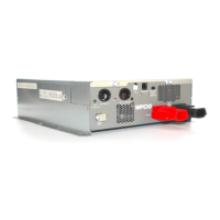
For operation in invert mode, the WF-5118/5120 Inverters require a nominal 12 VDC input from a house battery. The rear panel of the unit includes a convenient internal wiring box and hardwire output for these connections. The inverter's design incorporates advanced microprocessor control circuitry and a high-frequency switching mode power topology, which contribute to its efficiency and the quality of its output. The output waveform is a pure sine wave with a Total Harmonic Distortion (THD) of less than 3%, ensuring compatibility with sensitive electronics. The AC output voltage is regulated to ±3%, providing stable power. The system boasts better than 80% efficiency, minimizing energy loss.
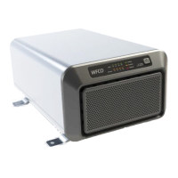
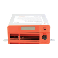
The WF-5118/5120 Inverters are equipped with several operational and safety features to enhance user experience and protect the unit and connected systems. These include a high surge current walk-in capability with a 3:1 crest factor, allowing it to handle loads with high initial power demands, and a high overload capability. A resettable circuit breaker is located on the rear panel for AC output protection. The front panel features an LED status display that provides visual feedback on the battery level, output load level, and operational mode. Both battery and load levels are displayed in four 25% increments, from 25% to 100%. The diagnostic display panel includes an AC Pass-Through LED (Green), an Operating on Battery LED (Amber), and a Fault LED (Red), along with an ON/OFF Power Pushbutton.
For remote control and monitoring, the inverters come with an optional remote switch panel. This panel mimics the front panel's status LEDs and includes an ON/OFF power pushbutton, allowing users to control and monitor the inverter from a distance of up to 32.8 feet (10 meters). It's important to note that for the remote panel to function, the main inverter's power pushbutton must be in the OFF position.
Safety is a paramount consideration in the design of these inverters. They feature DC Reverse-Polarity Battery Protection through internal fuses, which prevent permanent damage if the battery is connected incorrectly. However, these fuses are not user-replaceable, and a blown fuse necessitates inverter replacement. Over-Temperature Protection automatically shuts down the unit if its internal temperature exceeds a critical point, illuminating the Red Fault LED on both the front panel and remote switch. To restart, users must remove or reduce the AC load and cycle the power button. Electronic Current Limiting is another protective feature; if the AC output current exceeds the maximum rating in invert mode, the unit shuts down, and the Red Fault LED illuminates. Reducing the connected load and cycling the power button will restart the inverter.
Short-Circuit Protection is implemented for both Pass-Through and invert modes. In Pass-Through mode, a short circuit may trip the external AC supply breaker or the inverter's rear panel breaker. In invert mode, the internal protection circuitry shuts down the unit, and the Red Fault LED illuminates. Over/Under Input Protection ensures the inverter operates within a safe DC input range of 10-15 VDC. If battery voltage falls below 11.0 volts, a "Low Battery" symbol appears, and the unit will shut down if the voltage drops below 10 VDC. Similarly, if the voltage exceeds 15 VDC, the inverter shuts down to protect its internal circuitry. The AC output is further protected by a 20A/120 VAC resettable circuit breaker on the rear panel for the WF-5118 and WF-5120 models.
Internal cooling is managed by four DC brushless fans: two on the rear panel and two on the front panel, ensuring optimal operating temperatures. Installation involves mounting the enclosure in an accessible area near the house battery, ensuring free airflow for cooling and access to controls. AC ground bonding connects the AC input and output grounds to the inverter, while neutral grounding automatically connects the AC output circuit's neutral to the safety ground during inverter operation, adhering to National Electrical Code requirements.
For DC wiring, a UL-listed 250 Amp DC rated slow blow fuse or circuit breaker must be installed in the Positive battery cable within 18 inches of the battery to protect against damage and voiding the warranty. The inverters require 2/0 AWG copper wires for DC connections, with cable lengths kept as short as possible to maximize battery voltage at the inverter terminals. Proper torque (45 in-lbs) is crucial when connecting the Positive (Red) and Negative (Black) DC input lugs to prevent performance issues and heat build-up. An 8AWG copper wire is also required for chassis grounding.
Maintenance procedures include checking the fluid level in any battery connected to the RV charging system on a monthly basis when using a battery with the inverters. Troubleshooting guides are provided for common issues such as reverse polarity, incorrect DC input voltage, lack of pass-through functionality, and remote switch problems. These guides help users diagnose and resolve issues by checking connections, circuit breakers, and LED indicators. For instance, if the inverter has no pass-through, users are advised to check the rear panel circuit breaker and verify 115 VAC input. If the remote switch doesn't work, checking the cable connections and ensuring the main power pushbutton is in the OFF position are key steps. If the unit has pass-through but no power output with the power button ON, disconnecting the negative wire for 5 minutes to normalize internal circuitry and then reconnecting it is recommended. These comprehensive features and guidelines ensure reliable and safe operation of the WF-5118/5120 True Sine Wave Inverters.
| Output Voltage | 115 VAC |
|---|---|
| Output Frequency | 60 Hz |
| Power Output | 1000W |
| Continuous Power | 1000 Watts |
| Operating Temperature | 0°C to 40°C |
| Protections | Overload, Short Circuit, Over Temperature |