Inverter Power Mode
When incoming AC power is not available, and the Power Pushbutton is in the ON
position, the inverter will produce AC voltage at the output.
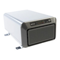
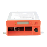
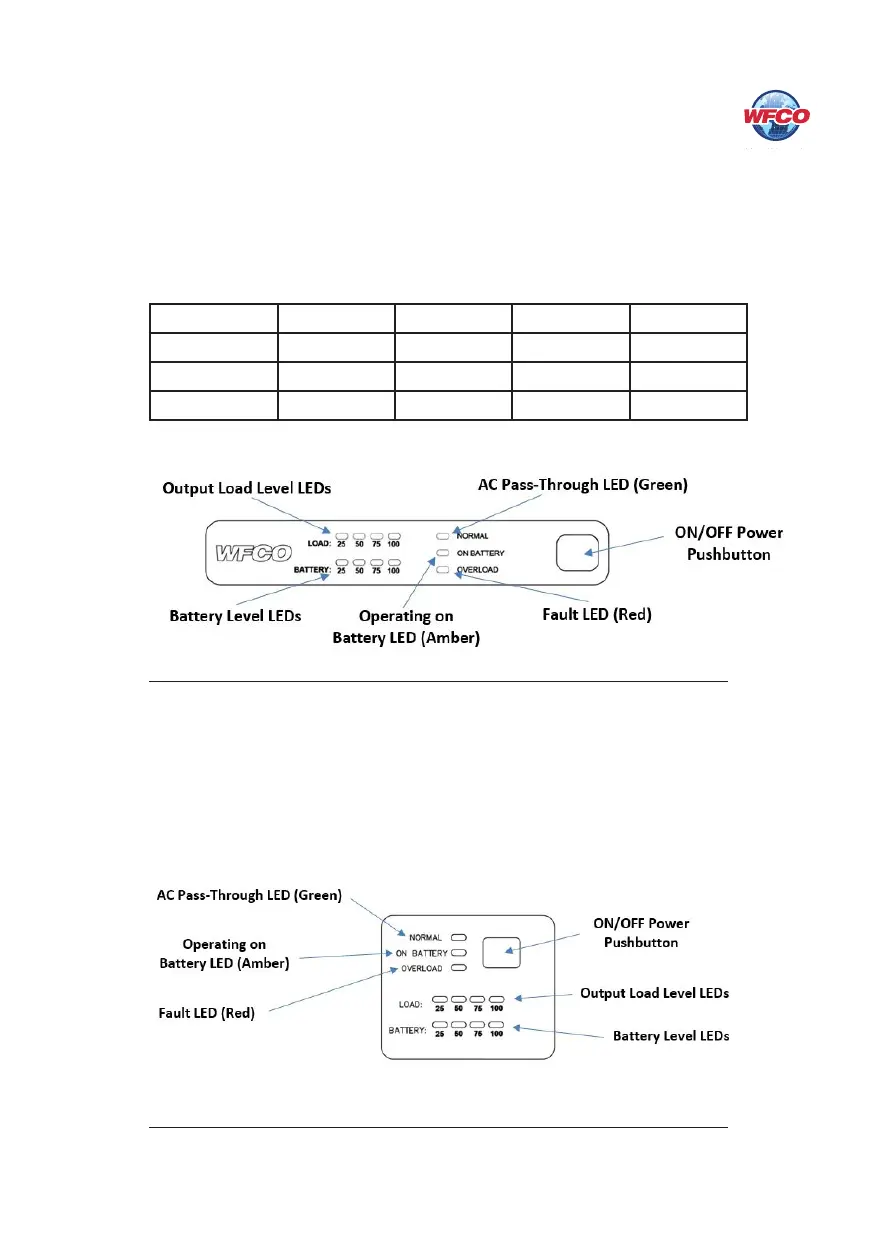
Diagnostic Display Panel
e WF-5118 and WF-5120 Inverters have front panel LEDs to indicate the output load
being supplied, current battery level, and operational mode of the inverter. Both the output
load level and battery level are displayed in four 25% increments, from 25% to 100%.
Percentage
25% 50% 75% 100%
Battery
>10.5 VDC >11 VDC >11.7 VDC >12.5 VDC
WF-5118 Load
3.75 A 7.5 A 11.25 A 15.0 A
WF-5120 Load
4.17 A 8.34 A 12.5 A 16.67 A
Remote Switch Panel
e WF-5118/5120 Inverters have a remote switch panel that provide status information and
ON/OFF control of the unit from a remote location. e WF-5118 and WF-5120 remote can
be located up to 32.8’ (10m) away from the main inverter unit. In addition to the ON/OFF
power pushbutton, the faceplate mimics the status LEDs found on the main inverter units
front panel. See the Diagnostic Display Panels section above for a description of the status
LEDs. NOTE: As above, the main inverter unit’s power pushbutton must be in the OFF
position for the remote panel to function.
7
Figure 4
Figure 5
 Loading...