15
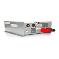
+12 VDC Input
Using a 14mm wrench, remove one of the two Positive (Red) lug nuts from the Red DC
power block on the inverter’s rear panel. Route the Red Positive battery cable through the
Red exible lug insulator and attach it to the Positive battery lug on the inverter. Torque
this lug to 45 in-lbs. NOTE: Using the proper torque to secure this connection is
important. A loose connection can cause inverter performance issues and may lead to
excessive heat build-up and damage to the unit. Slip the insulator over the lug ends and
press to secure in place.
DC Negative Input
Using a 14mm wrench, remove one of the two Negative (Black) lug nuts from the
Black DC power block on the inverter’s rear panel. Route the Black Negative battery
cable through the Black exible lug insulator and attach it to the Negative battery lug
on the inverter. Torque this lug to 45 in-lbs. NOTE: Using the proper torque to secure
this connection is important. A loose connection can cause inverter performance issues
and may lead to excessive heat build-up and damage to the unit. Slip the insulator over
the lug ends and press to secure in place.
Other Connections
Chassis Ground
Using a 5/32” hex wrench, loosen the Ground lug screw located on the mid le side of the rear
panel. Insert an 8AWG copper wire from this lug to chassis ground. Tighten the lug securely.
Remote Switch Cable
e Remote switch is an optional device that is included with the WF-5118 and WF-5120
Inverters. If remote operation of the WF-5118/5120 Inverter is desired, mount the Remote
switch within 32.8’ of the inverters rear panel. Using a 2 ¼” hole saw, make a cutout in the
cabinet or wall where the switch is to be located.
Using the supplied connecting cable, attach the DB9 connector to the DB9 connector on the
right side of the inverter’s rear panel. Route the cable through the RV to the Remote switch
mounting location. Plug the 10-position single row connector into the back of the Remote
switch. Attach the switch to the cabinet or wall with 4 screws (not supplied).
 Loading...