DC WIRING CONNECTIONS
Battery Cables
During high power operation, the battery cables to the inverter will see a very high current which
will cause some voltage drop. This voltage drop represents power loss, and if it’s too high it can
aect the surge power capability of the inverter.
The best solution is to position the inverter close to the batteries (as previously stated, if
lead-acid batteries are used, they need to be in a separate compartment). If they are within a
few feet, then cables with suitable ampacity will work well, with low voltage drop (less than 2%).
But if the
inverter is more distant from the batteries, then a larger gauge wire may be needed to prevent
excessive voltage drop. Use only high-quality copper wire.
The positive battery connection requires a fuse or circuit breaker that is within 18 inches of the
battery or its cable entrance to the vehicle. The fuse rating should conform with safety stan-
dards and be determined according to the specied wire ampacity. Suggested wiring and pro-
tection for the WF-5318 and WF-5320 is shown in Figure 11.
ITEM WF-5318 WF-5320
Rated Continuous Current 180 200
Minimum Safety Ground Wire Size 8 AWG 8 AWG
Minimum Dc Wire Size 2/0 2/0
90 degrees C insulation 105 degrees C insulation
Maximum Dc Fuse Size 195 amps 225 amps
Figure 11. Dc wiring suggestion for WF-5318 and WF-5320.
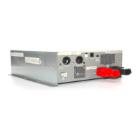
The cables from the battery and fuse are connected to the positive and negative bolt
terminals on the inverter. Be sure to observe correct polarity; the red terminal is positive (12
volts) and the black terminal is negative. The bolt terminals should be tightened to 6 ft-lbs or
8.1 Nm
maximum torque.
Rubber covers are provided for the terminations; slip these over the cable ends before
attaching the cables, then after the connections are secured, the cover can be moved over the
terminals for insulation and protection.
17
 Loading...