AC WIRING CONNECTIONS
CAUTION!
The electrical installation must conform to the local electrical codes and should be carried
out by a certied technician.
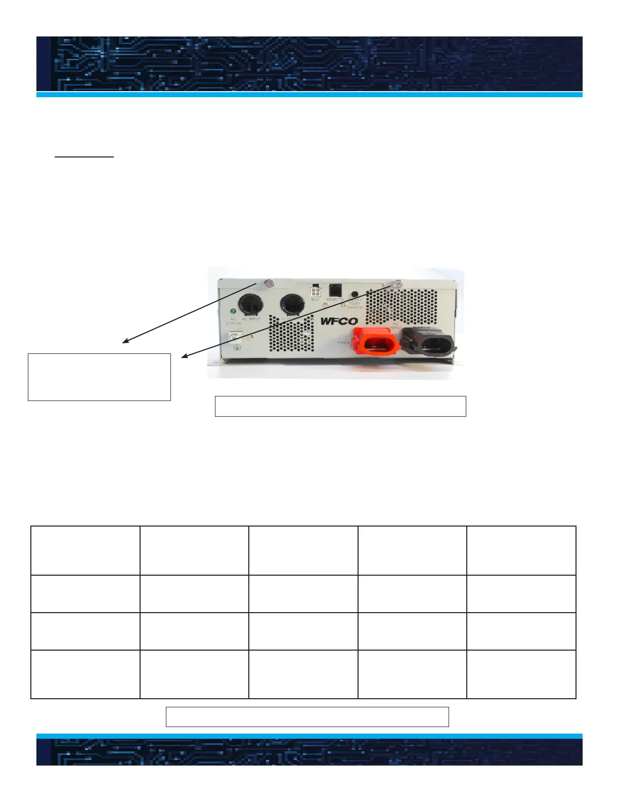
To access the ac wiring compartment, loosen the two thumb screws as shown in Figure 12,
tilt the cover, and pull it out with care.
These screws are captive.
Do not seperate from the
cover
Connect ac output and ac input wiring to the correct terminals using the lever terminals. Each line,
ground, and neutral wire must be correctly installed at the correct terminal. See Figure 13 for the
wire colors, which must be followed for all of the ac wiring.
Figure 12. Ac wiring connection to access panel.
Figure 13. Ac wire color, circuit breaker, and wire gauge
19
Conductor Wire Color For 15 Amp
Inverter/Bypass
Circuit
For 20 Amp
Inverter/Bypass
Circuit
For 25 Amp
Inverter/Bypass
Circuit
Line (L) Black Use 15 A Breaker
& 14 AWG Wire
Use 20 A Breaker
& 12 AWG Wire
Use 25 A Breaker
& 10 AWG Wire
Neutral (N) White Use 15 A Breaker
& 14 AWG Wire
Use 20 A Breaker
& 12 AWG Wire
Use 25 A Breaker
& 10 AWG Wire
Ground (G) Bare copper,
green, or green w/
yellow stripe
Use 15 A Breaker
& 14 AWG Wire
Use 20 A Breaker
& 12 AWG Wire
Use 25 A Breaker
& 10 AWG Wire
 Loading...