CONTROL PANEL LOCATION AND MOUNTING
The control panel is designed to be mounted in a wall; it can be positioned in any convenient
location that can be reached from the inverter by its cable. The included cable is 20 feet (6 m)
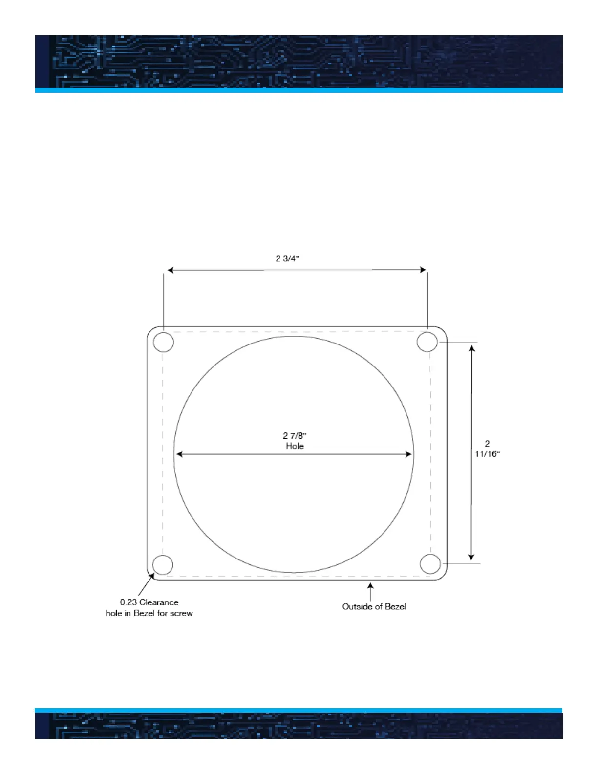
or 30 feet (9 m) long, depending on the model. The cutout for mounting the control panel can
be made with a 2-7/8” diameter hole saw. The panel is secured to the wall with four #10 or
#12 screws. See Figure 6 for control panel dimensions and Figure 9 for the mounting cutout
pattern
Figure 10. Panel Mounting Pattern
16
 Loading...