To tthe ffitter:
Ensure all relevant personnel read the points listed below and that a copy is passed on
to the end user.
To tthe eend uuser:
Read the points listed below before installation and use of equipment.
Read all instructions carefully before installing and using this product to ensure safe
installation and optimal performance. To prevent personal injury, disconnect the
power source when installing or servicing this product. Always remove the boat from
the water before using AC power tools. Use the fuse amperage rating specified for
your pump model (see table). Failure to do so may result in serious personal injury or
fire hazards.
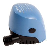
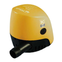
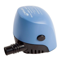
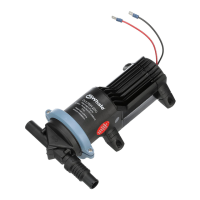
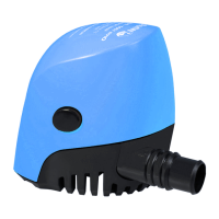
This Whale Orca Electric Bilge Pump is designed for use as a bilge pump in marine ves-
sels to pump fresh/grey water only.
DO NOT use pump to remove gasoline, oil or other flammable liquids. This pump is
designed to exhaust STANDING WATER ONLY. It is not intended to prevent rapid
accumulation of on-board water due to rough weather, hull damage and/or other
unsafe navigational conditions.
.
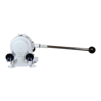
• Position pump in the lowest accessible part of the bilge. On sailboats, location
should be centred over keel (Figure 1).
• Do not mount the pump directly onto hull. Attach base strainer to a marine
plywood mounting pad that is fibreglassed to the hull.
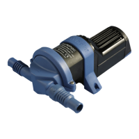
IMPORTANT: To prevent airlock, hose must rise continually upward to the thru-hull
connector with no dips or sharp bends. Hose support clips should be used at regular
intervals where necessary.
• Orientate the pump outlet for a direct, to ensure an unobstructed hose path.
• Secure all connections with hose clamps.
• If no thru-hull connector exists, install at 12" (25mm) minimum height above water
line. Apply marine sealant around thru-hull flanges on interior and exterior of hull.
CAUTION: Do not drill through the hull. Before drilling, ensure that the mounted pump
will be correctly positioned with pump nozzle pointing towards thru-hull connector.
(see figure 1).
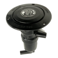
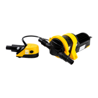
To remove pump body, place hand over body, depress locking tabs (eyes) and lift
body from strainer base. Note: Motor will be removed with body. (see figure 2).
• Use base as template to mark 3 mounting holes in mounting pad.
• Remove base. Drill three
1
/
8
" (3mm) pilot holes at marked locations.
• Replace base. Attach with #8 stainless steel fasteners (not supplied).
• Re-attach pump body to base. Insert body into strainer base, until base tabs snap
into holes in body. (see figure 2).
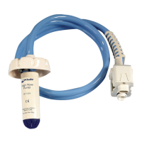
Ensure all wire connections are at the highest level above water. Use marine grade
wire connectors only and 16 SWG tinned copper wire. Waterproof all connections with
suitable materials. (see figure 3).
• Connect positive (+) brown wire to switch. For automatic operation, use an
Automatic Float Switch (whale product code: BE9010). Connect negative (-) black
wire to ground.
• Install fuse holder within 72" (183 cm) of the positive (+) battery terminal.
• To test system, feed water into the pump. If flow rate appears to be low, be sure
wires have been connected properly: Brown-to-positive (switch) and black-to-
negative. Reversed wiring reduces performance and can cause pump failure.
Disconnect power to the pump. Regularly remove motor housing and inspect and
clean filter to be sure that it is not being blocked by debris.
If ppump rruns bbut ddoes nnot ppump wwater:
• Check for airlock. Ensure that outlet hose runs upward to the thru-hull connector,
with no dips (see figure 1).
• Remove pump housing from base. Remove debris from chamber and impeller.
Ensure that the impeller is firmly attached to shaft and is not cracked or broken
(see figure 2).
If ppump ddoes nnot rrun:
• Check fuse.
• Be sure electrical connections and fuse are waterproof and have not loosened
(see figure 3).
OOrrccaa EElleeccttrriicc BBiillggee PPuummpp
Principles of Operation
Warning
MMooddeell
500 US GPH
(32 l/min)
950 US GPH
(57 l/min)
1300 US GPH
(82 l/min)
PPrroodduucctt CCooddee
BE0500 BE0950 BE1450 BE1454
OOppeenn FFllooww RRaattee @@
1133..66 VV..dd..cc
500 GPH
(32 l/min)
950GPH
(57 l/min)
1300GPH
(82 l/min)
FFllooww RRaattee @@
11mm ((33fftt)) HHeeaadd
450 GPH
(26 l/min)
850 GPH
(52 l/min)
1100 GPH
(65 l/min)
NNoommiinnaall VVoollttaaggee
12 Vd.c. 24 Vd.c.
CCuurrrreenntt DDrraaww
1.5 A 3.5 A 5.0 A 2.5 A
RReeccoommmmeennddeedd
FFuussee
2.0 A 5.0 A 7.0 A 5.0 A
WWeeiigghhtt
0.28 kg 0.45 kg 0.82 kg
HHoossee CCoonnnneeccttiioonnss
3
/
4
" (20 mm) 1
1/
8
”
(29.5 mm) 1
1/
8
”
(29.5 mm)
WWiirree SSiizzee
16 SWG x 2m (6 ft)
MMaatteerriiaallss
Pump body: ABS, Seals: Nitrile, Impeller: Acetal
MMaaxxiimmuumm
DDiisscchhaarrggee HHeeaadd
3.0 m (9.8 ft) 3.5 m (11.5 ft) 4.5 m (14.8 ft)
AABBYYCC SSppeecciiffiiccaattiioonnss
@@ 1133..66 VV..dd..cc..
((UUSS GGPPHH == GGaall ppeerr hhoouurr))
IISSOO SSppeecciiffiiccaattiioonnss
@@ 1122 VV..dd..cc..
((LLPPHH == LLiittrreess ppeerr hhoouurr))
PPaarrtt
NNuummbbeerr//
SSeerriieess
OOuuttlleett
HHoossee
II..DD..
AAmmpp
FFuussee
00 fftt..
HHeeaadd
GGPPHH//
aammppss
33..33 fftt..
HHeeaadd
GGPPHH//
aammppss
66..77 fftt..
HHeeaadd
GGPPHH//
aammppss
00kkPPaa
HHeeaadd
LLPPHH//
aammppss
1100kkPPaa
HHeeaadd
LLPPHH//
aammppss
MMaaxxiimmuumm
HHeeaadd
((fftt..@@1133..66vv//
kkPPaa@@1122vv))
BBEE00550000
3
/
4
" (20mm)
2.5A 500 450 300 118 107 3.0 / 27
BBEE00995500
3
/
4
" (20mm) 4A 950 800 550 225 190 3.5 / 32
BBEE11445500
1
1/
8
”
(29.5mm) 5A 1300 1100 760 308 285 4.5 / 40
BBEE11445544
1
1/
8
”
(29.5mm) 5A 1300 1100 760 308 285 4.5 / 40
Technical Specifications
Munster Simms Engineering Ltd,. Old Belfast Road, Bangor, Co Down, N.Ireland BT19 1LT
Tel: +44 (0)28 9127 0531 Fax: +44 (0)28 9146 6421
Web: www.whalepumps.com Email info@whalepumps.com
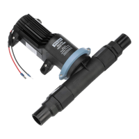
Hose Connection
Press both buttons
to release cover
Pull up cover to
remove
Wiring Instructions
Location
Pump Mounting
Maintenance and Troubleshooting
brown
wire
black wire
power
source
negative
positive
2- terminal
on - off switch
fuse holder
TTyyppiiccaall WWiirriinngg EExxaammppllee**
Suitable mounting pad
NN..BB..
hose must rise
upwards with
NNOO
dips
skin fitting
NN..BB
. outlet
must be a
minimum of
12” above the
water line
Application
FFiigg.. 11
FFiigg.. 33
FFiigg.. 22
* Flowrates are stated in accordance with ABYC recommendations at the design voltage of 13.6 V.d.c.