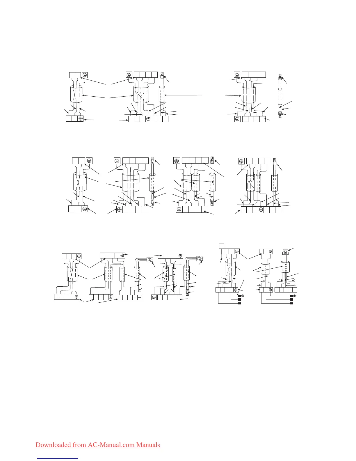
EasyManua.ls Logo

Whirlpool AMD 302 - Wiring Diagrams and Notes

Whirlpool AMD 302
18 pages
Print Icon
To Next Page IconTo Next Page
To Previous Page IconTo Previous Page
Loading...
18
Connect diagram
1500-4600W Model (5000-12000BTU/h Model)
5000-5100W Model (17000-18000BTU/h Model)
6000-7000W Model (21000-24000BTU/h Model)
NOTE:
If you find the colour of the connecting cable differs from the diagram on the previous page, refer to
actual model.
In any case, the terminal with the same sign must be connected to the connecting cable with the same
color.
If signal cable must be purchased separately, choose electric cable above 0.75mm.
If the interconnection cable for the power supply has to be replaced, please refer to the following table.
The plug housing 1 is connected to the matched receptacle housing of the indoor unit.
The plug housing 2 is connected to the matched receptacle housing of the outdoor unit.
1
1
1
1
5
5
1
1
Brown
Blue
Indoor unit terminal
Connecting
cable
Yellow/Green
Outdoor unit terminal
Cool only type
Brown
Blue
Black
Heat pump type
Plug housing 1
Yellow/Green
Gray
Brown
Blue
Heat pump typeor
Indoor unit terminal
Connecting
cable
Blue
Brown
Yellow/Green
Gray
Black
Brown
Blue
Outdoor unit terminal
Plug housing 1
Plug housing 2
1
1
1
1
5
5
1
1
1
1
Cool only type
Indoor unit terminal
Connecting
cable
Yellow/Green
Outdoor unit terminal
Brown
Blue
Blue
Brown
Black
Heat pump type Heat pump type Heat pump typeoror
Plug housing 1
Brown
Blue
Yellow/Green
Plug housing 2
Gray
Connecting
cable
Plug housing 1
Indoor unit
terminal
Plug
housing 2
Outdoor unit terminal
Brown
Brown
Blue
Plug housing 1
Yellow/Green
Blue
Blue
Brown
/
1
1
/
1
/
/
/
/
1
/
R1
R2
N N
L L
1
/
1
1
/
/
/
1
/
/
/
/
/
/
R1
R2
1
/
Y
1
/
Cool only type
Heat pump type
Heat pump type
or
Brown
Black
Indoor unit
terminal
Blue
Yellow/Green
Outdoor unit
terminal
Connecting cable
Brown
Blue
Yellow/Green
Brown
Blue
Gray
Brown
Black
Yellow/Green
Connecting cable
Plug housing 1
Indoor unit terminal
Blue
Brown
Gray
Outdoor unit
terminal
Plug housing 2
Black
Brown
Connecting cable
Plug housing 1
Black
Brown
Blue
Brown
Blue
POWER
SOURCE
Outdoor
unit terminal
Brown
Blue
Yellow/Green
Connecting cable
Indoor unit
terminal
Brown
Yellow/Green
Blue
Brown
POWER
SOURCE
Blue
Black
Gray
Plug
housing 1
Cool only type (T3) Heat pump type (T3)
Blue
Brown
Downloaded from AC-Manual.com Manuals

Related product manuals