EasyManua.ls Logo

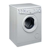
Whirlpool AWM 243 User Manual

Whirlpool AWM 243
10 pages
To Next Page IconTo Next Page
Page #1 background imageLoading...
Page #1 background image
SERVICE
Whirlpool Europe
Customer Services
Model AWM 243
Version 8570 243 42001 Page
Technical data 2 - 3
Spare part list 4 - 5
Exploded view 6 - 7
Wiring diagram 8
Circuit diagram 9
Program diagram 10
Family 1A
Service Manual
Washing machine
Frontloader
AWM 243
AWM 243
This documentation is only intended for qualified technicians who are aware of the respec-
tive safety regulations.
Date: 23.07.1999 Subject to modification
Document-No.: 4812 712 14543
Question and Answer IconNeed help?

Do you have a question about the Whirlpool AWM 243 and is the answer not in the manual?

Whirlpool AWM 243 Specifications

General IconGeneral
BrandWhirlpool
ModelAWM 243
CategoryWasher
LanguageEnglish

Summary

Technical Data Overview

Dimensions and Weight

Physical dimensions (height, width, depth) and weight of the washing machine.

Electrical and Drum Specifications

Main electrical connections, drum volume, and spin speed details.

Laundry Capacity and Water Levels

Maximum load for different fabric types and water quantities for wash/rinse.

Component Specifications

Details on pressostat, door lock, heating element, inlet valve, and drain pump.

Program Timer and Motor

Electromechanical timer functions, motor details, and related components.

Control Components

Variable thermostat, push button functions, and electrical output terminals.

Spare Parts Identification

Cabinet and Structural Parts

List of spare parts for the cabinet, frame, and exterior components.

Internal Components and Hoses

Spare parts for internal mechanisms, plumbing, and hoses.

Electrical and Control Parts

Spare parts for electrical components, sensors, and control elements.

Miscellaneous Components

Spare parts for accessories, mounting kits, and minor fixings.

Exploded Views

External and Drum Assembly

Diagram showing external parts, door, drum, and related mounting.

Internal Component Layout

Diagram illustrating the arrangement of internal electrical and mechanical parts.

Rear and Base Components

Exploded view of components located at the rear and base of the machine.

Wiring Diagram

Circuit Diagram Analysis

Program Sequence and Timing

Program Flow and Timer Steps

Detailed sequence of operations for various wash programs.

Program Options and Settings

Explanation of available program options and control settings.

Related product manuals