PA
GE 5
FOR SERVICE TECHNICIAN’S USE ONLY
DO NOT REMOVE OR DESTRO
Y
SOFTW
ARE VERSION DISPLAY MODE
To access Software V
ersion Display Mode, perform steps 1 and 2
of Activating the Service Diagnostic Test Modes. Toggle the cycle
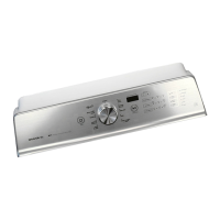
selector knob until the status LEDs correspond as follows:
“Rinse, Final Spin, and Done” LEDs On
NOTE: Status LED names may vary between makes and models.
Press the START button to begin software display mode.
Upon entering the software version display mode, the
Major
, Minor
, and Test version numbers for the software are
displayed by alternating the state of the Status LEDs in one
second intervals; the process repeats following a pause.
To calculate the number being displayed, add the
representative numbers together that are displayed at the
same time; see chart below for representative numbers.
For example, if the s/w version is 02.01.07, the following
sequence would be displayed:
16 8 4 2 1
02
01
07
Press and hold the START button for 3 seconds at any time
to exit software version display mode.
FACTORY DIAGNOSTIC
S
This is for factory use only, as it runs the F
actory Cycle
Template for testing the washer before it leaves the factory.
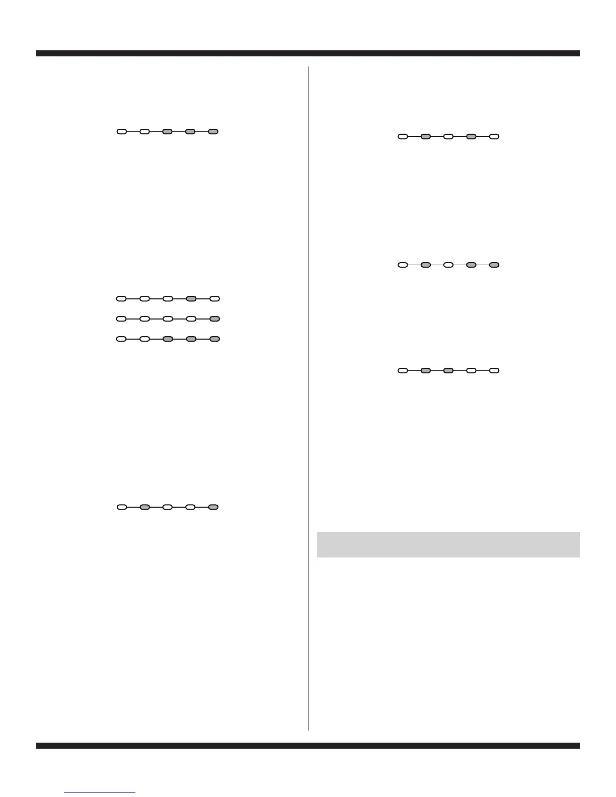
TACHOMETER VERIFICA
TION MODE
To access T
achometer Verification Mode, perform steps 1 and
2 of Activating the Service Diagnostic Modes. Toggle the cycle
selector knob until the status LEDs correspond as follows:
“Soak/Wash and Done” LEDs On
NOTE: Status LED names may vary between makes and models.
Press the START button to begin tachometer verification mode.
Tachometer verification uses the status LEDs to represent
the tachometer frequency (basket RPM).
For example, slowly turn the basket by hand; as the basket
turns, the DONE
, FINAL SPIN, RINSE, and SOAK/WASH
status LEDs will illuminate one at a time in a visually repeating
cycle. The LED timing is derived from the tachometer signal
itself.
Press and hold the START button for 3 seconds at any time
to exit tachometer verification mode.
DRY FACTORY DIAGNOSTIC
S
This cycle is used by the factory to gather data for setting the
proper algorithms. This cycle is the same for all washers and
may indicate that some switches or valves are actuated that
are not used. T
oggle the cycle selector knob until status LEDs
correspond as follows:
NOTE: This cycle should not be used as a field diagnostic test.
While running the Dry Factory cycle, the control is also
enabling the UI Diagnostics test.
FACTORY CALIBRA
TION TEST
This cycle is used by the factory to test functions and intervals
specifically for functionality testing of specific components, and
gathering data. Toggle the cycle selector knob until status LEDs
correspond as follows:
NOTE: This cycle should not be used as a field diagnostic test.
CLEAN WASHER CY
CLE
Puts washer into the W
asher Cleanout Cycle. To access the
Clean Washer Cycle, perform steps 1 and 2 of Activating the
Service Diagnostic Test Modes. Toggle the cycle selector knob
until status LEDs correspond as follows:
NOTE: This cycle should not be used with anything still loaded
in the wash basket.
CUSTOMER VIEWABLE F
AULT CODES
There are 3 fault codes that may be visible to the customer
indicated by the following Status LEDs:
SOAK/WASH LED ON (Long Fill F
ault) – Refer to “No Fill,
Long Fill” on page 7 for information.
FINAL SPIN LED ON (Long Drain F
ault) – Refer to “Long
Drain” on page 7 for information.
LID LOCKED LED FLASHING CONTINUOUSL
Y (Lid Lock
Fault) – Refer to “Lid Lock Fault” on page 6 for information.
FOR SERVICE FAULT AND ERROR CODES,
CONTINUE TO PAGES 6 AND 7
Sensing Soak/ Final
Load Wash Rinse Spin Done
Se
nsing
Soak/ Final
Load Wash Rinse Spin Done
Sensing Soak/ Final
Load Wash Rinse Spin Done
Sensing Soak/ Final
Load Wash Rinse Spin Done
Sensing Soak/ Final
Load Wash Rinse Spin Done
Sensing Soak/ Final
Load Wash Rinse Spin Done