PAGE 18
FOR SERVICE TECHNICIAN’S USE ONLY
DO NOT REMOVE OR DESTROY
Pressure Switch (Non-Steam Models)
This test checks the pressure switch, CCU,
and wiring. NOTE: Usually, if the pressure
switch malfunctions, the washer will generate
a long fill or long drain error.
1. Check the functionality of the pressure
switch by running a small load cycle. The valves
should turn off automatically after sensing the
correct water level in the tub. The following
steps assume that this step was unsuccessful.
2. Press START/PAUSE to stop the cycle and
then press POWER. The cycle will cancel and
drain the water from the tub.
3. Unplug washer or disconnect power.
4. Remove top and rear panels to access tub,
air trap, and pressure hose connections. Pressure
switch is located at top right rear of cabinet.
5. Check connections from tub to air trap,
air trap to pressure hose, and pressure hose
to pressure switch.
6. Check to ensure hose is routed correctly in
the lower cabinet and not pinched or crimped.
7. Verify there is no water, suds, or debris
in the hose or air trap. Disconnect hose from
pressure switch and blow into hose to clear
water, suds, or debris.
8. Check hose for leaks. Replace if needed.
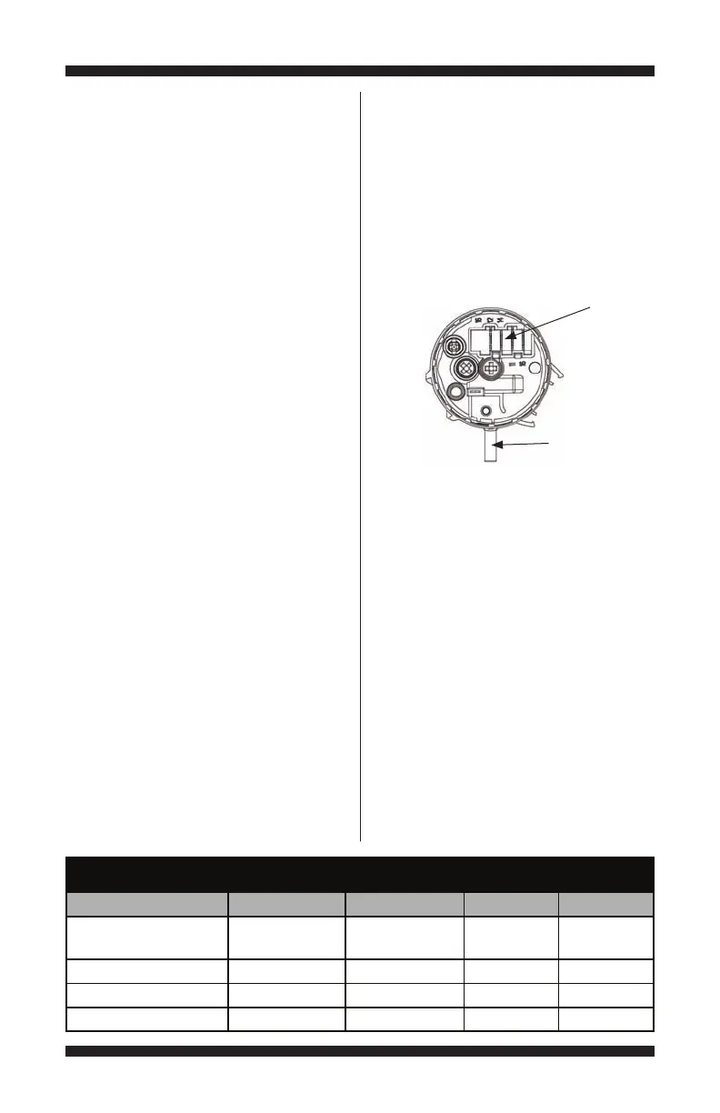
Figure 8 - Pressure Switch
Heater Trip Wash Level Vcc Overflow
CCU PS8 Pinout 6543
Press Sw Pinout 12 14 11 16
No Pressure Closed Open Ref Open
Light Pressure Open Closed Ref Open
Medium Pressure Open Closed Ref Closed
Pressure Switch Check
4. Remove top and rear panels to access tub,
air trap, and pressure hose connections. Pressure
sensor is located at top right rear of cabinet.
5. Check connections from tub to air trap,
air trap to pressure hose, and pressure hose
to pressure sensor.
6. Check to ensure hose is routed correctly in
the lower cabinet and not pinched or crimped.
7. Verify there is no water, suds, or debris
in the hose or air trap. Disconnect hose from
pressure sensor and blow into hose to clear
water, suds, or debris.
8. Check hose for leaks. Replace if needed.
9. Visually check that connector PS8 is
inserted all the way into the CCU (refer to
CCU diagram on page 13). Also check that
the pressure sensor harness is securely
connected to the sensor.
10. Check the harness between the CCU and
Pressure Sensor for continuity.
If there is continuity, go to step 11.
If there is no continuity, repair or replace
as necessary.
11. Plug in washer or reconnect power.
12. With a voltmeter set to DC, connect black
probe to CCU connector PS8, pin 8 (GND) and
red probe to PS8, pin 4 (+5V [Vcc]).
If +5V DC is present, replace the pressure
sensor.
If+5V DC is not present, perform TEST
#1: CCU Power Check on page 13.
13. If the preceding steps did not correct the
problem, replace the CCU.
Unplug washer or disconnect power.
Replace the CCU.
Reassemble all parts and panels.
Perform the “Quick Diagnostic Test”
on page 6 to verify repair.
Pressure Switch
Harness Connector
Pressure Hose
Connector
 Loading...