This document is a service manual for a Whirlpool Refrigerator, model WSN11W, intended for export and printed in November 2005. It provides detailed specifications, wiring diagrams, refrigerant circuit information, troubleshooting guides, and replacement procedures for various parts.
Function Description
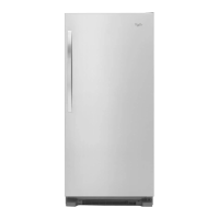
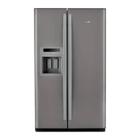
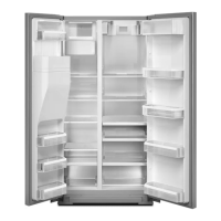
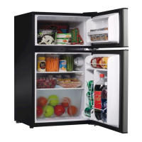
The WSN11W is a 2-door, no-frost refrigerator designed for household use. It features an electronic thermostat for automatic temperature control and an automatic defrost system that utilizes heat transfer from the compressor. The refrigeration system uses HFC-134a refrigerant.
Important Technical Specifications
General:
- Model: WSN11W
- Classification: 2 Doors No Frost
- Temperature Control: Thermostat Electronic
- Defrost System: Automatic (Heat by transfer from the compressor)
- Drain: Aluminum Coil With Bond
- Condenser: Copper Tube Inside
- Insulation: Rigid Polyurethane Foam (HCFC-141b) for Cabinet, Freezer Door, and Refrigerator Door
- Refrigerant: HFC-134a
- Refrigerant Charge: 105 g
- Overall Dimension (WxDxH): 606 x 670 x 1,522 mm
- Packing Dimension (WxDxH): 657 x 749 x 1,635 mm
- Net Weight: 65.0 kg
- Gross Weight: 65.0 kg
- Power Source: 220V / 50Hz
- Power Cord: C4
- Internal Volume (Litre): 284 (by ISO 8561;1995)
Operating Temperature (°C) at 1013hPa (mb) (Thermostat MM1-8612):
- Warm (ON): -3 ± 3 °C
- Normal (ON): -9 ± 1.1 °C
- Cold (OFF): -25 ± 2.2 °C
- Normal (OFF): -18 ± 1.1 °C
Electrical Parts (Model WSN11W):
- Compressor: C-BZN152L6Z
- Power Supply Range: 220V / 50 Hz
- Resistance (Room temp 25°C):
- Main Wiring: 11.94 Ω (Approx.)
- Auxiliary Wiring: 18.39 Ω (Approx.)
- Abnormal: Open (∞ Ω) or Short Circuited (0 Ω)
- Starting Relay: PTH7M220MC1
- Resistance (Room temp 25°C):
- Normal: 22 Ω ± 20% (Approx.)
- Abnormal: Open (∞ Ω) or Short Circuited (0 Ω)
- Overload Protector: 4TM734RHBYY-53
- Resistance (Room temp 25°C):
- Normal: Less than 1 Ω (Approx.)
- Abnormal: Open (∞ Ω) or Short Circuited (0 Ω)
- Interior Light: 240 V / 15 W
Usage Features
The refrigerator is designed for ease of use with its electronic thermostat and automatic defrosting, minimizing manual intervention for temperature management and maintenance. The 2-door configuration allows for separate access to the freezer and refrigerator compartments.
Maintenance Features
The service manual provides comprehensive instructions for troubleshooting and replacing various components, making maintenance straightforward for trained technicians. Key maintenance procedures include:
Thermostat Replacement:
- Remove Ice Cube Box, Tray, and Tray Chiller.
- Remove Freezer Corner.
- Adjust Knob Thermo to "Min" position.
- Pull out Thermo.
- Release screws at FF. Cover and lift the cover.
- Pull out Thermostat socket.
- Release Thermostat's lock.
- Pull out Thermostat from Plate MTG Motor.
- Pull out electrical wire from Thermostat by gripping the plug.
- Reverse the steps for reassembly.
Fan Replacement:
- Follow steps 1-8 of thermostat replacement.
- Dig Spring.
- Pull out Fan from Fan Motor.
- Reverse the steps for reassembly.
Fan Motor Replacement:
- Follow steps 1-9 of thermostat replacement.
- Press Plate MTG Motor to remove lock.
- Lift Plate MTG Motor out.
- Return the Plate MTG Motor to show the behind side.
- Hold Recept Terminal and pull out electrical wire from Fan Motor.
- Dig Spring.
- Pull out Fan from Fan Motor.
- Release screw at Cover A.
- Pull fan motor from Plate MTG Motor.
- Separate Fan Motor from Cover A.
- Pull Back Grommet from Fan Motor.
- Reverse the steps for reassembly.
Glass Tube Heater Replacement:
- Follow steps 1-11 of Fan Motor replacement.
- Hold the socket of Glass Tube Heater and pull out.
- Use a small steel stick to press at the Recept Terminal while pulling out the electrical wire.
- Pull out electrical wire from the socket.
- Hold and lift Evaporator up.
- Remove aluminum tape covering the electrical wire.
- Hold Glass Tube Heater at the rubber connector.
- Reverse the steps for reassembly.
Bimetal Thermostat Replacement:
- Follow steps 1-11 of Fan Motor replacement.
- Pull out the socket of Bimetal Thermostat.
- Use a small steel stick to press at the Recept Terminal while pulling out the electrical wire.
- Pull out electrical wire from the socket.
- Cut out Cable Tie from Evaporator tube.
- Remove Bimetal Thermostat.
- Reverse the steps for reassembly.
Thermal Fuse Replacement:
- Follow steps 1-11 of Fan Motor replacement.
- Pull out the socket of Thermal Fuse.
- Use a small steel stick to press at the Recept Terminal while pulling out the electrical wire.
- Pull out electrical wire from the socket.
- Cut out Cable Tie from Evaporator tube.
- Remove Thermal Fuse.
- Reverse the steps for reassembly.
Damper Thermostat Replacement:
- Pull out Tray Chiller.
- Release Door.
- Remove all Tray Chillers.
- Remove Shield Light from Cover Thermostat.
- Turn Knob Thermostat to "Min" position.
- Pull out Knob Thermostat from Cover Thermostat.
- Dig Cover Cap out.
- Release screw from Cover Thermostat.
- Lift out Cover Thermostat.
- Separate Insulation from Cover Thermostat.
- Remove paper tape from Insulation.
- Straighten Damper Thermostat sensing tube.
- Separate Insulation from each other.
- Release screws holding Damper Thermostat and Case Damper.
- Pull Damper Thermostat from Case Damper.
- Reverse the steps for reassembly.
Lamp Replacement:
- Follow steps 1-3 of Damper Thermostat replacement.
- Remove Shield Light from Cover Thermostat.
- Turn Lamp counterclockwise to remove.
- Reverse the steps for reassembly.
Door Switch Replacement:
- Dig door switch out.
- Pull door switch from Inner Box.
- Hold recept terminal.
- Reverse the steps for reassembly.
Timer Replacement:
- Release screws holding Rear Cover at Cabinet.
- Release screws holding Timer from the plate.
- Hold Recept Terminal and pull out electrical wires from Timer.
- Reverse the steps for reassembly.
Starting Relay Replacement:
- Release screws holding Rear Cover and Cabinet.
- Release Relay Cover Fixing Clip.
- Remove Relay Cover.
- Remove Starting Relay.
- Hold Recept Terminal and pull out electrical wires from Starting Relay.
- Reverse the steps for reassembly.
Overload Protector Replacement:
- Release screws holding Rear Cover and Cabinet.
- Release Relay Cover Fixing Clip.
- Remove Relay Cover.
- Remove Starting Relay.
- Remove Overload Protector.
- Hold Recept Terminal and pull out electrical wires from Overload Protector.
- Reverse the steps for reassembly.
Micro Switch Replacement:
- Unlock Dispenser Cover out.
- Remove Dispenser Cover from base.
- Use a screwdriver to unlock the housing connector of Micro Switch.
- Pull out housing of Micro Switch.
- Release screws of Micro Switch at Dispenser Cover.
- Pull out Micro Switch from Dispenser Cover.
- Reverse the steps for reassembly.
Motor Supply Pump Replacement:
- Remove Tank from water tube.
- Release screws at Motor Cover.
- Take Motor Cover from Door Liner.
- Release screws at Water Supply Pump.
- Pull out the housing from inner Door Liner.
- Use a screwdriver to unlock the housing connector of Water Supply Pump.
- Pull out housing of Water Supply Pump.
- Cut cable tie from Dispenser Tube A.
- Pull out Dispenser Tube A from Dispenser Tube A.
- Reverse the steps for reassembly.
Transformer Ass'y Replacement:
- Tilt the Refrigerator.
- Use a wrench to release screws.
- Release inner screws at Transformer Ass'y.
- Release screws holding Rear Cover at Cabinet.
- Release outside screws at Transformer Ass'y.
- Take Transformer Ass'y from plate cabinet base.
- Pull out housing of Transformer Ass'y.
- Pull out tape.
- Uncover plastic bag from wire set.
- Cut the wire joint.
- Pull out the Transformer Ass'y electrical wires.
- Reverse the steps for reassembly.
All maintenance procedures emphasize unplugging the power cord before servicing to ensure safety.