EasyManua.ls Logo

White Rodgers 1F56 Series User Manual

White Rodgers 1F56 Series
6 pages
To Next Page IconTo Next Page
Page #1 background imageLoading...
Page #1 background image
Printed in U.S.A.
PART NO. 37-6097A
9916
PRECAUTIONS
FAILURE TO READ AND FOLLOW ALL INSTRUCTIONS CAREFULLY
BEFORE INSTALLING OR OPERATING THIS CONTROL COULD CAUSE
PERSONAL INJURY AND/OR PROPERTY DAMAGE.
DESCRIPTION
Operator: Save these instructions for future use!
This low voltage thermostat is designed to provide conve-
nient control of the heating/cooling system. To provide
greater room comfort, the sensitive spiral bimetal is com-
bined with an adjustable heating anticipator and a fixed
cooling anticipator to provide maximum comfort.
1F56 Series
Low Voltage Heating/Cooling Thermostats
INSTALLATION INSTRUCTIONS
CONTENTS
Description ......................................................... 1
Precautions ........................................................ 1
Specifications..................................................... 2
Installation.......................................................... 2
Select Thermostat Location
Route Wires to Location
Attach Subbase to Wall
Special System Configurations
Electric Heat Furnaces (Single Trans-
former Systems Only)
Two-Transformer Systems
Heat Pump Applications
Special Application Terminals
Attach Thermostat to Subbase
Operation & Maintenance .................................. 5
Adjusting Heat Anticipator
Calibrating Thermostat
WHITE-RODGERS
WHITE-RODGERS DIVISION
EMERSON ELECTRIC CO.
9797 REAVIS ROAD
ST. LOUIS, MISSOURI 63123-5398
If in doubt about whether your wiring is millivolt, line, or low
voltage, have it inspected by a qualified heating and air
conditioning contractor, electrician, or someone familiar
with basic electricity and wiring.
Do not exceed the specification ratings.
All wiring must conform to local and national electrical
codes and ordinances.
This control is a precision instrument, and should be
handled carefully. Rough handling or distorting compo-
nents could cause the control to malfunction.
To prevent electrical shock and/or equipment
damage, disconnect electric power to system at
main fuse or circuit breaker box until installation
is complete.
Do not short out terminals on gas valve or pri-
mary control to test. Short or incorrect wiring will
burn out heat anticipator and could cause per-
sonal injury and/or property damage.
Do not use on circuits exceeding 30 volts. Higher
voltage will damage control and could cause
shock or fire hazard.
CAUTION
!
WARNING
!
Question and Answer IconNeed help?

Do you have a question about the White Rodgers 1F56 Series and is the answer not in the manual?

White Rodgers 1F56 Series Specifications

General IconGeneral
Power SourceBattery (2 AA)
Stages1 Heat/1 Cool
TypeNon-programmable
Voltage24 VAC
MountingWall

Summary

Description

Precautions

Electrical Shock and Equipment Damage Prevention

Prevent electrical shock and equipment damage by disconnecting power before installation.

Voltage Limit Warning

Do not use on circuits exceeding 30 volts to avoid damage and fire hazard.

Specifications

ELECTRICAL DATA

Details on switch rating, heating/cooling current, and switch action.

THERMAL DATA

Information on temperature range and differential settings.

APPLICATIONS

Intended uses and systems for the thermostat, including limitations.

Installation

SELECT THERMOSTAT LOCATION

Guidelines for choosing the optimal location for thermostat placement.

ROUTE WIRES TO LOCATION

Instructions for routing thermostat wires through walls and floors.

Attach Subbase to Wall

SPECIAL SYSTEM CONFIGURATIONS

Specific wiring instructions for electric heat and two-transformer systems.

Heat Pump Applications

Instructions for single-stage heat pump system wiring and terminal use.

ATTACH THERMOSTAT TO SUBBASE

Steps for physically connecting the thermostat to its subbase.

Typical Wiring Diagrams

Figure 3. Typical wiring diagram

General wiring overview showing terminal identification and hookup.

Figure 4. Single Transformer System Wiring

Wiring diagram for a single transformer heating/cooling system.

Figure 5. Two Transformer System Wiring

Wiring diagram for a two-transformer heating/cooling system.

Operation & Maintenance

Subbase switching and thermostat/system operation

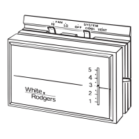
Explanation of how system and fan switches control operation.

Adjusting Heat Anticipator

Calibrating Thermostat

Related product manuals