Do you have a question about the White Rodgers 1F82-51 and is the answer not in the manual?
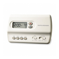
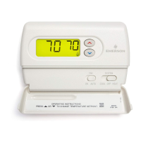
| Display | Digital |
|---|---|
| Stages | 1 Heat/1 Cool |
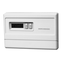
| Voltage | 24V AC |
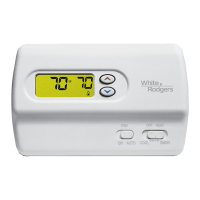
| Backlight | Yes |
| Temperature Range | 45° to 90°F (7° to 32°C) |
| Power Source | Battery |
| Compatibility | Single Stage Heat/Cool Systems |
| Type | Non-programmable |
To prevent electrical shock and/or equipment damage disconnect electric power to system at main fuse or circuit breaker box until installation is complete.
Do not use on circuits exceeding specified voltage. Higher voltage will damage control and could cause shock or fire hazard.
Electrical Rating: 20 to 30 VAC 50/60 Hz. or D.C. 0.05 to 1.5 Amps (Load per terminal)
Setpoint Temperature Range: 45°F to 90°F (7°C to 32°C)
For use with: Heat pump systems with up to two stages heat, one stage cool
Shut off electricity at the main fuse box until installation is complete. Ensure that electrical power is disconnected.
Remove the packing material from the thermostat.
Read the following information before clipping the non-electric heat jumper.
The EMR feature allows, the thermostat's microcomputer to automatically calculate the time it will take to change the room temperature.
The following wiring diagrams show typical terminal identification and wiring.
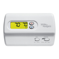
The O/B switch on this thermostat is factory set to the "O" position. This will accommodate the majority of heat pump applications.
Armchair Programming is a unique feature that allows your thermostat to be programmed before being mounted on the wall.
The first stage has anticipation that can be set to 2.5 or 4 cycles per hour for heating or cooling.
If at any time during testing, your system does not operate properly, contact a qualified serviceperson.
FOR QUALIFIED SERVICE TECHNICIANS' USE ONLY. OPERATORS SHOULD NOT USE THIS FEATURE DUE TO POSSIBILITY OF EQUIPMENT OR PROPERTY DAMAGE, OR PERSONAL INJURY.
This thermostat has a built-in short term (5-minute) time delay. During this 5-minute period, the thermostat will lock out the compressor to allow head pressure to stabilize.
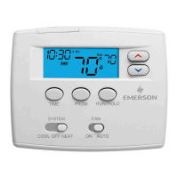
Other than the following buttons and switches are located behind the door on the bottom of the thermostat cover.
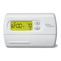
Indicates day of the week. Alternately displays current time and temperature.
Now that you are familiar with the thermostat buttons and display, read the following information to learn about the many features of the thermostat.
Follow these steps to enter the heating and cooling programs you have selected.
Move the SYSTEM switch to HEAT position.
If the outside temperature is below 50°F, disconnect power to the cooling system before programming.
Follow these steps to check your thermostat programming one final time before beginning thermostat operation.