EasyManua.ls Logo

White Rodgers 1F83-0471 User Manual

White Rodgers 1F83-0471
16 pages
To Next Page IconTo Next Page
Page #1 background imageLoading...
Page #1 background image
1
80 Series Thermostat with
Automatic Heat/Cool Changeover Option
Single Stage, Multi-Stage or Heat Pump
Installation and Operating Instructions for Model:
FAILURE TO READ AND FOLLOW ALL INSTRUCTIONS
CAREFULLY BEFORE INSTALLING OR OPERATING
THIS CONTROL COULD CAUSE PERSONAL INJURY
AND/OR PROPERTY DAMAGE.
Save these instructions for future use!
APPLICATIONS
SPECIFICATIONS
Electrical Rating:
Battery Power .................................................... mV to 30 VAC, NEC Class II, 50/60 Hz or DC
Input-Hardwire ................................................... 20 to 30 VAC
Terminal Load ........................................................... 1.5 A per terminal, 2.5A maximum all terminals combined
Setpoint Range ......................................................... 45° to 90°F (7° to 32°C)
Differential (Single Stage) ......................................... Heat 0.6°F; Cool 1.2°F (adjustable)
Differential (Heat Pump) ........................................... Heat 1.2°F; Cool 1.2°F (adjustable)
Operating Ambient .................................................... 32° to +105°F (0° to +41°C)
Operating Humidity ................................................... 90% non-condensing max.
Shipping Temperature Range ................................... -40° to +150°F (-40° to +65°C)
Dimensions Thermostat ............................................ 3-7/8”H x 5-1/8”W x 1-1/4”D
www.white-rodgers.com
www.emersonclimate.com
1F83-0471 Thermostat
Model Programming Choice
1F83-0471
Non-Programmable
ATTENTION: MERCURY NOTICE
This product does not contain mercury. However, this product
may replace a product that contains mercury.
Mercury and products containing mercury must not be
discarded in household trash. Do not touch any spilled
mercury. Wearing non-absorbent gloves, clean up any
spilled mercury and place in a sealed container. For proper
disposal of a product containing mercury or a sealed
container of spilled mercury, place it in a suitable shipping
container. Refer to www.white-rodgers.com for location to
send product containing mercury.
To prevent electrical shock and/or equipment damage,
disconnect electric power to system at main fuse or
circuit breaker box until installation is complete.
CAUTION
!
THERMOSTAT APPLICATION GUIDE
Description
Heat Pump (No Aux. or Emergency Heat) Yes
Heat Pump (with Aux. or Emergency Heat) Yes
Systems with up to 2 Stages Heat, 2 Stages Cool Yes
Heat Only Systems (with optional fan switch) Yes
Millivolt Heat Only Systems – Floor or Wall Furnaces Yes
Cool Only Systems Yes
Gas or Oil Heat Yes
Electric Furnace
Yes
Hydronic (Hot Water) Zone Heat – 2 Wires Yes
Hydronic (Hot Water) Zone Heat – 3 Wires Yes
Compressor with Comfort Alert II Module (1F85CA only) Yes
Index Page
Installation 2
Wiring Connections 2
Wiring Diagrams 3
Thermostat Quick Reference 4
Installer Configuration Menu 5
Operating Your Thermostat 7
Troubleshooting 7
PART NO. 37-7149B
Replaces 37-7149A
1014

Questions and Answers:

White Rodgers 1F83-0471 Specifications

General IconGeneral
BrandWhite Rodgers
Model1F83-0471
CategoryThermostat
LanguageEnglish

Summary

APPLICATIONS

Thermostat Application Guide

Lists compatible heating and cooling system types for the thermostat.

SPECIFICATIONS

IMPORTANT NOTICES

Electrical Safety Caution

Warning to disconnect power before installation to prevent shock or damage.

Mercury Handling Notice

Advises on handling mercury-containing products, as this unit may replace one.

INSTALLATION

Installation Safety Warning

Safety warning regarding Class II circuits per NEC code.

Removing and Installing Thermostat

Steps for removing the old unit and installing the new thermostat and batteries.

WIRING CONNECTIONS

Terminal Designation Descriptions

Explains the function of each terminal on the thermostat base.

WIRING DIAGRAMS

Heat Pump System Wiring

Details wiring for Heat Pump Type 1 and Type 2 systems.

Fossil Fuel System Wiring

Details wiring for Single Stage and Multi-Stage fossil fuel systems.

Zone Valve Wiring

Wiring diagram for a 3-wire heat-only zone valve application.

THERMOSTAT QUICK REFERENCE

Home Screen Overview

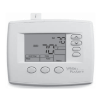
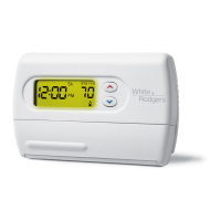
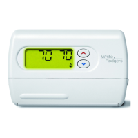
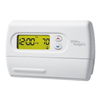
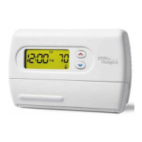
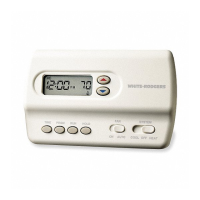
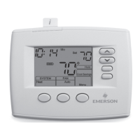
Explains the elements displayed on the thermostat's home screen.

Programming & Configuration Indicators

Describes various status messages and indicators on the thermostat display.

INSTALLER CONFIGURATION MENU

Configuration Menu Options Table

Table detailing configuration options, factory defaults, and their functions.

Keypad Lockout Configuration

How to enable and set a keypad lockout combination for security.

System Mode Configuration

Options for configuring system modes like Heat, Cool, Auto, or Heat Pump.

Temperature Limit Settings

Setting maximum heat and minimum cool setpoint limits.

Fast Stage Activation Settings

Enabling/disabling fast stage activation for heating and cooling.

Comfort Alert Protection Setup

Enables active protection to prevent compressor damage based on Comfort Alert module codes.

Filter Replacement Reminder Setup

Setting a reminder for filter changes based on runtime hours.

Reversing Valve Terminal Configuration

Configuring the O/B terminal for heat pump reversing valve control.

OPERATING YOUR THERMOSTAT

Fan Setting Selection

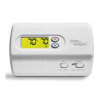
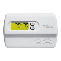
How to select between Auto and On fan modes.

System Setting Selection

How to select system modes like Heat, Off, Cool, Auto, or Emer.

TROUBLESHOOTING

Comfort Alert Diagnostic Codes

Explains diagnostic codes from the Comfort Alert module and their meanings.

Reset Operation and Troubleshooting

Procedures for resetting the thermostat and troubleshooting blank displays.

System Operation Issues

Addresses common problems like no heat/cool/fan, constant operation, and temperature swings.

Thermostat Accuracy and Lockout

Covers thermostat/thermometer discrepancies and how to reset forgotten keypad lockout codes.

Related product manuals