Do not use on circuits exceeding specified voltage.
Higher voltage will damage control and could cause
shock or fire hazard.
Do not short out terminals on gas valve or primary
control to test. Short or incorrect wiring will damage
thermostat and could cause personal injury and/or
property damage.
Thermostat installation and all components of the
system shall conform to Class II circuits per the NEC
code.
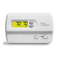
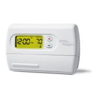
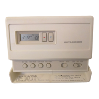
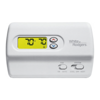
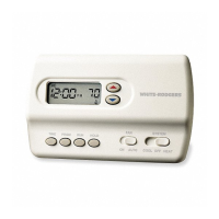
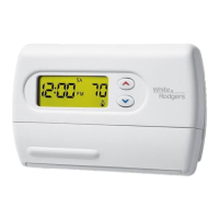
1F83-261
Non-Programmable Electronic Digital
Multi-Stage Thermostat
INSTALLATION AND OPERATION INSTRUCTIONS
FAILURE TO READ AND FOLLOW ALL INSTRUCTIONS CAREFULLY
BEFORE INSTALLING OR OPERATING THIS CONTROL COULD CAUSE
PERSONAL INJURY AND/OR PROPERTY DAMAGE.
DESCRIPTION
• Backlitdisplaywhenanykeyispushed
• °F/°Cconvertibility
• Temperaturerange45°to90°F
• R,C,W,W2,G,YandY2terminals
• OptionalCterminal(DualPoweroption)
• Setpointstorageincaseofpowerloss
• 2“AA”Energizer
®
alkalinebatteriesincluded
Operator: Save these instructions for future use!
YournewWhite-RodgersDigitalThermostatusesthetechnology
ofasolid-statemicrocomputertoprovideprecisetime/temperature
control.Thisthermostatoffersyoutheexibilitytodesignheating
andcoolingprogramsthattyourneeds.
Features:
• Simultaneousheatandcoolsetpointstorage
• Pre-settemperaturecontrol
• LCDcontinuouslydisplayssetpointandroomtemperature
PRECAUTIONS
Thisthermostatisintendedforusewithalowvoltagesystem;
donotusethisthermostatwithalinevoltagesystem.Ifindoubt
aboutwhetheryourwiringismillivolt,line,orlowvoltage,haveit
inspectedbyaqualiedheatingandairconditioningcontractor
orelectrician.
Donotexceedthespecicationratings.
Allwiringmustconformtolocalandnationalelectricalcodes
andordinances.
Thiscontrolisaprecisioninstrument,andshouldbehandled
carefully.Roughhandlingordistortingcomponentscouldcause
thecontroltomalfunction.
To prevent electrical shock and/or equipment damage,
disconnect electric power to system at main fuse or
circuit breaker box until installation is complete.
SPECIFICATIONS
ELECTRICAL DATA
Electrical Rating:
20to30VAC50/60Hz.orD.C.
0.05to1.5Amps(Loadperterminal)
1.5 Amps Maximum Total Load(Allterminalscombined)
THERMAL DATA
Setpoint Temperature Range:
45°Fto90°F(7°Cto32°C)
Operating Ambient Temperature Range:
32°Fto105°F
Operating Humidity Range:
0to90%RH(non-condensing)
Shipping Temperature Range:
-4°Fto150°F
APPLICATIONS
Forusewith:
• Heat/coolsystemswithuptotwostagesheat,
twostagescool
DO NOT USE WITH:
• Millivoltsystems
• Systemsexceeding30VACand1.5amps
• 3-wirezonedhydronicheatingsystems
PART NO. 37-6321B
Replaces37-6321A
1014
www.white-rodgers.com
www.emersonclimate.com