Printed in U.S.A.
FAILURE TO READ AND FOLLOW ALL INSTRUCTIONS CAREFULLY BEFORE
INSTALLING OR OPERATING THIS CONTROL COULD CAUSE PERSONAL
INJURY AND/OR PROPERTY DAMAGE.
DESCRIPTION
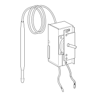
Type 2B61 and 2B62 Remote Bulb Thermostats are designed
for use on a wide variety of heating equipment and appliances,
and are especially suitable for electric heating. Extremely com-
pact in size, these snap-action thermostats are suitable for use
on both inductive and non-inductive loads.
When the temperature of the liquid or air surrounding the bulb
rises, the switch contacts open to turn off the heat. When the
temperature drops the contacts close to turn on the heat.
INSTALLATION INSTRUCTIONS
TYPE 2B61 & 2B62
SNAP ACTION
REMOTE BULB THERMOSTAT
PART NO. 37-5539A
Replaces 37-9245
9523
WHITE-RODGERS DIVISION
EMERSON ELECTRIC CO.
9797 REAVIS RD., ST. LOUIS, MO. 63123
(314) 577-1300, Fax (314) 577-1517
9999 HWY. 48, MARKHAM, ONT. L3P 3J3
(905) 475-4653, FAX (905) 475-4625
PRECAUTIONS
To prevent electrical shock and/or equipment damage,
disconnect electric power to system at main fuse or
circuit breaker box, until installation is complete.
All wiring must conform to local and national electrical codes and
ordinances.
This control is a precision instrument, and should be handled
carefully. Rough handling or distorting components could cause
the control to malfunction.
SPECIFICATIONS
Switch Action: Open on rise, snap-action
Contact Structure:
Type 2B61: – Single Pole
Type 2B62: – Double Pole
Maximum Ambient:
Temperature Switch: 150°F (66°C)
Electrical Rating
INDUCTIVE RATING
NON-INDUCTIVE
TYPE RATING FULL LOAD LOCKED ROTOR
NUMBER
120V 240V 120V 240V 120V 240V
2B61 25A 25A 10A 6A 60A 36A
2B61 – 25A 10A 6A 60A 36A
These controls have been accurately calibrated at the factory.
Any attempt to calibrate these controls voids the White-Rodgers
warranty.
The switch mechanism of this control may be mounted in any
location, provided that the temperature and humidity of the air in
which it is located do not cause a condensation on the switch
parts.
If the equipment manufacturer has made provisions for location
of the switch and control bulb, follow his instructions. If none are
provided, the following general rules should be observed:
NOTE
1. The control bulb should be located in an area of average
temperature of the medium being controlled.
When used to sense air temperature (as in an electric
heater) the bulb should be located so that the return air to the
heater flows freely over the bulb. The bulb should be fas-
tened away from the cabinet of the heater so that it senses
air temperature, and not cabinet temperature.
When used to control a liquid bath, be sure that the bulb is
fully immersed in the liquid. Also be sure that the bulb is
located where it can sense average temperature of the liquid.
INSTALLATION
WHITE-RODGERS
Operator: Save these instructions for future use!