43WIKA operating instructions pressure transmitter, model IS-3
MM/YYYY country code based on 14095850.02 12/2014 EN/CN
EN
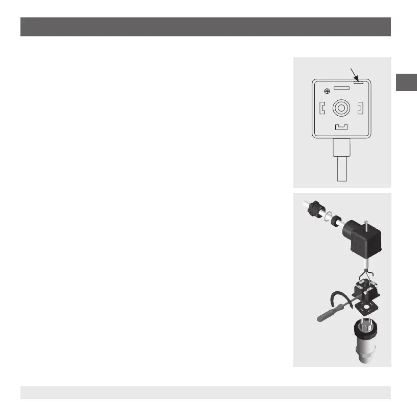
Fitting a DIN 175301-803 angular connector
1. Loosen the screw (1).
2. Loosen the cable gland (2).
3. Pull the angle housing (5), with the terminal block (6) inside, away from the
instrument.
4. Via the mounting hole (D), lever the terminal block (6) out of the angle housing
(5). Do not try to push the terminal block (6) out using the screw hole (1) or the
cable gland (2), otherwise the sealing of the angle housing could be damaged.
5. Select a conductor with an outer diameter matched to the angle housing's
cable gland. Slide the cable through the cable gland (2), washer (3), gland seal
(4) and angle housing (5).
6. Connect the cable ends to the appropriate connection terminals on the termi-
nal block (6) (see table “Electrical connections”).
7. Press the angle housing (5) onto the terminal block (6).
8. Tighten the cable gland (2) around the cable. Make sure that the seals are not
damaged and that the cable gland and seals are assembled correctly in order
to ensure ingress protection.
9. Place the at, square gasket over the pressure transmitter's connection pins.
10. Slide the terminal block (6) onto the pressure transmitter's connection pins.
11. Secure the angle housing (5) and terminal block (6) to the pressure transmitter
with the screw (1).
6. Commissioning, operation
(5)
(1)
(2)
(3)
(4)
(D) Mounting hole
 Loading...