Night Scan Chief
Revision 1 ii
7. SOFTWARE REVISIONS 7-1
7.1 Introduction ......................................................................................................................................... 7-1
8. APPENDICES 8-2
LIST OF ILLUSTRATIONS
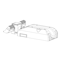
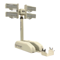
Figure 1-1 Night Scan Chief Base and Remote Control Positioner..............................................................1-1
Figure 1-2 Mast Loads .................................................................................................................................. 1-1
Figure 2-1 Lifting Point.................................................................................................................................. 2-2
Figure 2-2 Night Scan Base Mounting Hole Locations................................................................................. 2-3
Figure 2-3 Standard Junction Box ................................................................................................................2-3
Figure 2-4 Junction Mounting Hole Locations............................................................................................... 2-4
Figure 2-5 Hand Held Receptacle Pins......................................................................................................... 2-5
Figure 2-6 Example of Warning Light Installation ......................................................................................... 2-6
Figure 3-1 Actuator and Proximity Sensors ..................................................................................................3-2
Figure 3-2 Photo Interrupter and Flag........................................................................................................... 3-3
Figure 3-3 Cover and Screw Removal for Manual Stow (Night Scan Chief only) ........................................ 3-7
Figure 4-1 Proximity Switch Adjustment ....................................................................................................... 4-3
Figure 4-2 LED Location and Function ......................................................................................................... 4-3
Figure 4-3 Flag Settings................................................................................................................................ 4-5
Figure 4-4 DIP switch location: Chief base board......................................................................................... 4-6
Figure 4-5 DIP switch location: Chief RCP board......................................................................................... 4-6
Figure 4-6 NFPA Handheld Remote Wiring.................................................................................................. 4-7
Figure 4-7 Non-NFPA Hand Held Remote Wiring ........................................................................................ 4-7
Figure 4-8 Night Scan Chief Base Wiring ..................................................................................................... 4-8
Figure 4-9 Night Scan Chief Remote Control Positioner (RCP) Schematic ................................................. 4-9
Figure 5-1 Exploded View - Base Left Side .................................................................................................. 5-2
Figure 5-2 Base Right Side........................................................................................................................... 5-3
Figure 5-3 Exploded View – Mast Pivot Assembly ....................................................................................... 5-3
Figure 5-4 Exploded View - Remote Control Positioner (RCP) .................................................................... 5-5
LIST OF TABLES
Table 1-1. Reference Data Night Scan Chief.................................................................................................. 1-2
Table 2-1. Tools and Materials Required for Installation ................................................................................ 2-1
Table 2-2. Handheld Remote Control Connector Pin-out............................................................................... 2-5
Table 4-1. List of Base Board Faults.............................................................................................................4-10
Table 4-2. List of Remote Control Positioner Board Faults .......................................................................... 4-14
Table 4-3. List of Remote Control Board Faults............................................................................................ 4-17
Table 4-4. List of Warning Codes ................................................................................................................. 4-18
Table 4-5. Mechanical Troubleshooting........................................................................................................4-19
Table 5-1. Night Scan Chief Base Assembly Parts List.................................................................................. 5-1
Table 5-2. Remote Control Positioner Assembly Parts List............................................................................5-4
Table 7-1. Software Revision Log................................................................................................................... 7-1