14
INSTALLING
YOUR FURNACE
Vent Installation
The vent installation must comply with all local codes and
ordinances. If in doubt, consult your local codes or inspector.
The furnace vent must be directed to the outdoors so that
harmful combustion gases will not collect inside the building.
This furnace must not be connected to a chimney flue
serving a separate solid-fuel burning appliance.
This product is design certified to ANSI Z21.86. It must be
installed with a U.L. tested and listed type “B” approved vent
and type “B/W” approved vent (Figure 8). Older style terra-cotta,
transite, clay, concrete or masonry type vent pipe cannot be
used with this appliance. These types of vent pipe will not heat
fast enough to establish a draft, which will result in improper
venting of combustion products. Consequently, this could
cause the vent safety control system to shut down the furnace.
The area above header within the stud space MUST be kept
clear of any attic insulation to allow the free circulation of air
around the oval vent piping. In some areas the building code
requires the use of an attic shield.
The B/W vent must extend through the ceiling and roof
terminating at least 12-feet above the finished floor on
which the furnace rests.
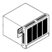
Install Furnace vent
Attach a 4-foot length of oval, double-wall vent pipe through
the plate spacers to the hold-down plate. Push the vent pipe
into the hold-down plate until it is completely seated. The
hold-down cleat will engage the groove in the vent pipe.
Complete the venting
Type B/W gas vent shall extend from the header plate of the
furnace to a point above the highest ceiling plate within the
stud space through which the vent passes, without any offsets
or crossovers. The first vent pipe offset, (if required), may not be
any closer than 2-feet from the header and needs to extend
past the ceiling plate. After a type B/W gas vent passes through
the highest ceiling plate within a stud space above the furnace
to which it serves, the vent system may be completed with a
Type B gas vent, from the SAME manufacturer (do not mix
brands of pipe). Offsets cannot be greater than 45 degrees
from vertical. Refer to The Uniform Mechanical Code.
Install the oval-to-round adapter. Complete the piping
extending it through the roof. Use a 4-inch round, double-
wall (Type B) vent pipe, roof flashing, storm collar and vent
cap as shown. The vent cap must be at least 2-feet higher
than any point that is within 10- feet of the vent cap. There
must be at least a 1-inch clearance between the vent pipe
and any combustible material.
CAUTION: To avoid damage to wiring, be sure to route the
wires away from the path of the furnace vent.
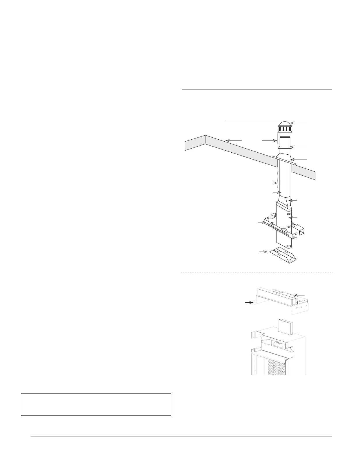
FIGURE 8 – Typical Vent Installation
VENT CAP MUST BE MINIMUM 2 FEET
HIGHER THAN ANY POINT WITHIN
10 FEET OF THE VENT CAP
10 FEET
LISTED
VENT CAP
STORM
COLLAR
ROOF
FLASHING
HEIGHT FROM HEADER PLATE
TO THE VENT CAP TOP MUST
BE 6 FEET MINIMUM
1 INCH MIN. CLEARANCE TO COMBUSTIBLES
LISTED 4 ROUND B VENT
OVAL TO ROUND
ADAPTER
OVAL BW VENT
DOUBLE WALL
PLATE SPACER
RECESSED MOUNT
2 REQUIRED
BASE PLATE HOLD DOWN
OR STARTER PLATE SCREWED
DOWN TO HEADER PLATE
50,000 BTUHR. MODEL SERIES
AND HEADER NOT SHOWN
NOTE: THESE PARTS ARE
SUPPLIED WITH THE FURNACE
HEADER PLATE AND GASKETS
PROVIDED WITH FURNACE
GASKET