16
INSTALLING
YOUR FURNACE
Attaching Your Furnace continued
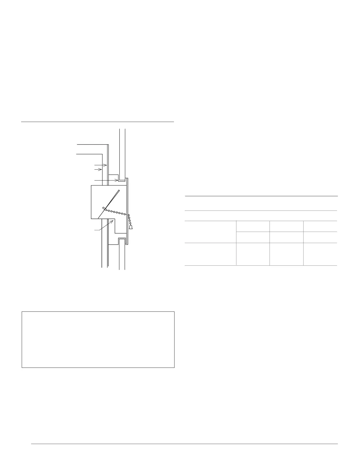
After furnace is in position, install rear outlet register as shown
in Figure 12. Have damper in open position when inserting
the assembly. Secure the rear outlet register to speed nuts
with the machine screws furnished.
FIGURE 12 – Mounting Rear Outlet Register
Gas Supply and Piping
The gas control valve, in the furnace, is shipped with a seal
over the gas inlet tapping. Do not remove the seal until ready
to connect the piping.
WARNING: Danger of property damage, bodily injury or
death. Make sure the furnace is equipped to operate o
the type of gas available. Models designed as natural gas
are to be used with natural gas only. Models designed for
use with liquefied petroleum (L.P.) gas have orifices sized
for commercially pure propane gas. They cannot be used
with butane or a mixture of butane and propane.
Gas Supply
For natural gas, the minimum inlet gas supply pressure for
the purpose of input adjustment is 5-inches water column.
The maximum inlet gas supply pressure is 7-inches water
column.
Gas pressure and input to the burners must not exceed
the rated input and pressure shown on the nameplate.
The natural gas manifold pressure should be 4-inches
water column.
The gas supply line must be of adequate size to handle the
BTU/hr. requirements and length of the run for the unit
being installed.
Determine the minimum pipe size from Figure 13, based
on the length of the run from the gas meter to the unit.
All piping must comply with local codes and ordinances
or with the National Fuel Gas Code (ANSI Z223.1 NFPA No.
54), whichever applies. (In Canada: CAN/C.GA B149). Refer
to FIGURE 14 for the general layout of the unit. It shows the
basic fittings needed.
The following rules apply:
1. Use new, properly reamed steel or black iron pipe and
fittings free of metal chips and debris that are approved by
local codes. Metal chips and debris can damage the valve.
2. Do not thread pipe too far. Valve distortion or malfunction
may result from excess pipe within the gas control valve.
Apply a moderate amount of good quality dope to the
pipe only. Leave the two end threads bare. (Figure 15). 3.
Use ground joint unions.
4. Install a drip leg (sediment trap) to trap dirt and moisture
before it can enter the gas valve. The nipple must be a
minimum of 3-inches long.
5. Install a manual shutoff valve.
6. Provide a 1/8” NPT test gauge connection immediately
before the gas supply connection to the furnace.
Gas connection
Use two pipe wrenches when making the connection to the
valve to prevent turning and/or damage to the valve.
FIGURE 13 - Pipe Capacity
FURNACE SHIELDS
REAR REGISTER
OUTLET
PLASTER GROUND
Orifice Sizes
The efficiency rating of this appliance is a product thermal
efficiency rating determined under continuous operating
conditions and was determined independently of any
installed system.
This furnace is equipped with a computer controlled
modulating valve and power burner. For elevations above
2,000 feet, adjust thermostat settings to the appropriate
elevation during installation.
Pipe Capacity - BTU/HR. with Fittings
Natural Gas
Pipe Size
Length of
Pipe - Ft.
1/2 3/4 1
92,000
63,000
50,000
190,000
130,000
105,000
350,000
245,000
195,000
20
40
60