10
INSTALLING
YOUR FURNACE
WARNING: Danger of illness, bodily injury or death. Draft
hood spillage, with unobstructed vents, indicates that
additional air must be brought into the structure from
the outside. Keep a window open (minimum 2-inches
near the appliance until a permanent air duct is installed.
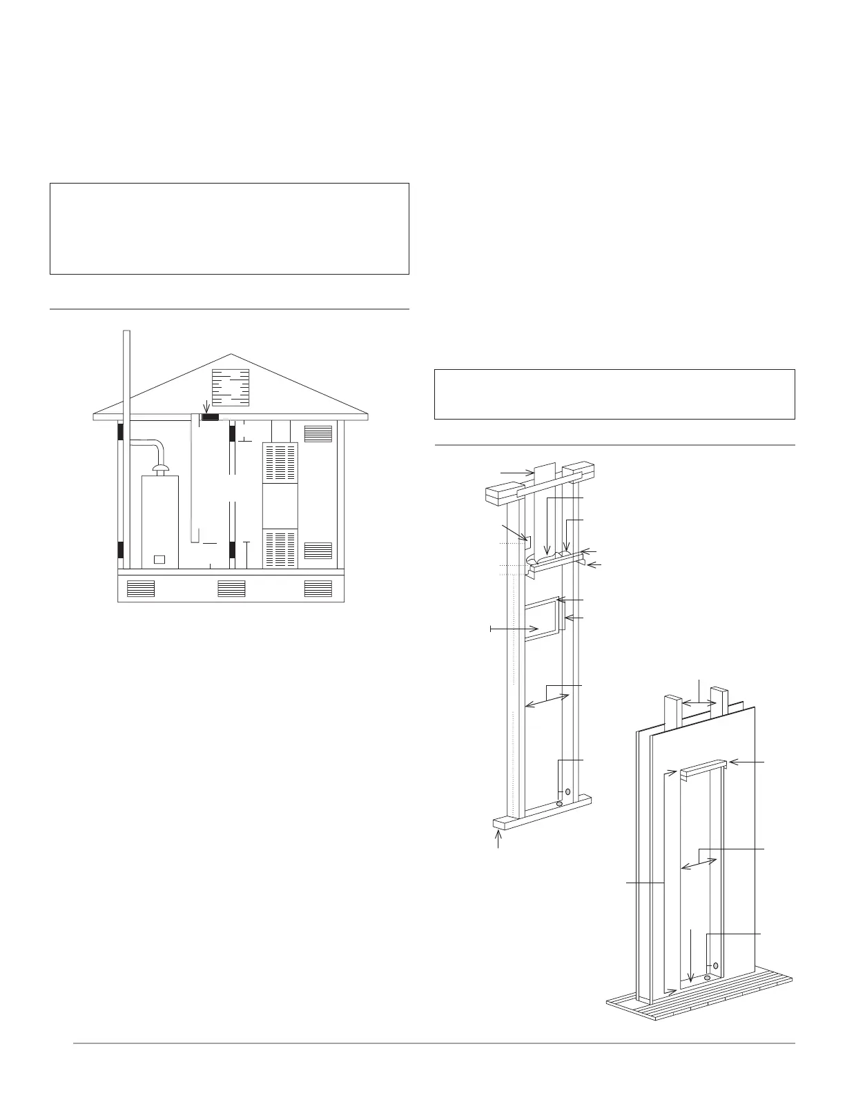
FIGURE 5- Recessed Wall Mount Installation
Examples of Air Inlets and Outlets
Recessed Wall Mount
Installation
The maximum recess depth from rear of furnace forward
is 4½-inches.
Find the studs and ceiling joints
Use a stud locater or small finishing nails. Repeatedly drive and
remove a nail into the wall in the area of the stud until it
is located. Then find the inside edge of the stud. Leave the
nail at this location.
The other stud should be about 14½-inches from the one
found. Drive finishing nails on the inside of this stud. Draw wall
cutout to required size as shown in Figure 5. If wall studs are not
on 16-inch centers. See “CLOSE OFF STUD SPACE.” (Figure 6).
Cut wall opening
Cut wall opening 14⅜-inches wide and 66⅛-inches high
measured from the top of the floor plate. (Figure 5). All corners
must be square.
Installation of rear outlet register
The optional rear outlet register may be installed when the
furnace is recessed into the wall. In new construction, install
the rear outlet plaster ground at the same time you install the
header plate. For existing construction, make the necessary
CHIMNEY OR GAS VENT
VENTILATED
ATTIC
OUTLET AIR
OUTLET AIR
INLET AIR
INLET AIR
VENTILATED
CRAWL SPACE
10 CRAWL
SPACE
WALL
FURN
TO
ATTIC
12
OPTIONAL INLET AIR 1 SO
INCH PER 4,000 BTUH
100 SQ
INCHES
EACH
1 SQ INCH
PER 4,000 BTUH
MAX
12
2 x 4 STUDS
TOP OF
HEATER
FINISHED
FLOOR
2 X 4
FLOOR
PLATE
14 3/8
66 1/8
GAS STUB
LOCATION
B-W VENT
BASE PLATE
PLASTER TO TOP OF HEADER PLASTER GROUND
REAR REGISTER OPTIONAL FOR SINGLE
BURNER MODELS ONLY
PLASTER GROUND
NAIL FLANGE
8 18 X 13 14
CUTOUT
REAR
OUTLET
REGISTER
OPENING
115.V OUTLET
FOR OPTIONAL
BLOWER
TOP OF HEADER
2 x 4
PLATE
ALTERNATE
GAS STUB
LOCATION
14 3/8
A = 4
MODELS
20,500 &
35,000
BTUHR.
A = 2 58
MODELS
50,000
BTUHR.
BOTTOM OF HEADER NAILING FLANGE
9 18
62 14
3 3/4
cutout and install the plaster ground before you install the
furnace. See instructions packed with accessory and Figure 5.
Do not allow wall finish material to project into the
furnace recess.
Do not install rear outlet register where grille may be blocked
by a door, curtains or any other obstruction.
Gas supply opening
A hole must be drilled for the gas line. Decide whether the
gas line will come through the floor or wall. Drill a 1½-inch
hole through the floor or wall as needed. (Figure 5).
CAUTION: Be careful not to damage any furnace
components while making any alternate hole.