24
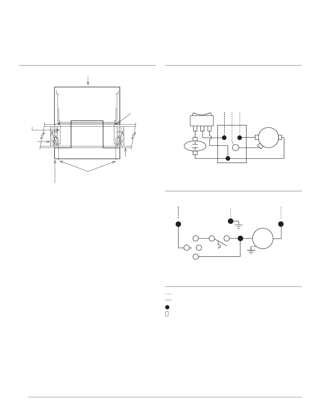
FIGURE F – Wiring
FIGURE E – Surfaced Mounted Installation
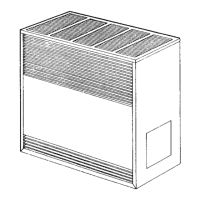
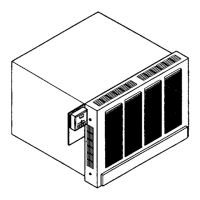
SURFACE MOUNTED FURNACE
SCREW #10 24 X 4.50 PHIL HD
REGISTER
ASSEMBLY
2 X 4
STUD
SUPPORT
BRACKET
SPEED
NUT 4
DRY WALL
+
SWITCH LEGEND
1 ON
2 OFF
3 AUTO
1 2 3
FAN
SWITCH
HOT
GND
NEUT
BLOWER
MOTOR
HEAT
SENSOR
SWITCH
BL
R
R
W
GND
BK
BK
G
115V 60Hz
HOT NEUT
GND
BL
HEAT
SENSOR
SWITCH
BLOWER
MOTOR
GND
FAN
SWITCH
BKW BK
R
1
2
3
R
LEGEND
high voltage field
high voltage factory
wire connector for line voltage - factory wiring
14 quick connect terminals for factory wiring connections.
BK = BLACK
BL = BLUE
W = WSHITE
R = RED
G = GREEN
NOTES:
1. Motor is thermally protected.
2. If any of the original wire as supplied with the appliance must be replaced, it
must be replaced with (105') wire or it’s ewq1ivalent.
Total electrical load less than 3 AMPS.