English
12 WILO SE 11/2010
Installation and operating instructions
Keys to the figures:
General keys
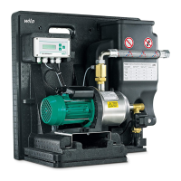
1Cistern
2Float switch
3Floating extractor
4Filter
5Suction line
6 Public water supply
7 Switchgear RainControl Basic (RCB)
83-way valve
9 Pressure and flow controller Ecocontrol
9a Display (mains on/ power on)
9b Display (Pump in operation/ Pump on)
9C Display (fault)
9D Commissioning- and fault acknowledgement
button RESET
9E Neutral conductor pump
9F Phase pump + return signal RCB
9G Earthing pump
9 h Earthing RCB
9 I Neutral conductor RCB
9 k Phase RCB
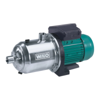
10 Pump
11 Connection of the overflow (DN75)
12 Connected load on pressure side
13 Additional earthing
14 AF Basic
15 Cap
16 DN25 - G1" connection suction line
17 Rp 1" connection on the pressure side
18 G 3/4" connection to public water supply
19 Overflow
20 Connecting cable to power supply
(length: 1.80 m)
21 Filling the pump
22 Replenishment reservoir (11 l)
Fig. 3
PE Earthing
X1 LPhase
N Neutral conductor
N Neutral conductor additional pump
L1 Phase additional pump
x2 1 Pressure and flow controller Ecocontrol L
2 Pressure and flow controller Ecocontrol N
3 Pressure and flow controller Ecocontrol U
x2 4 3-way valve feed mode
5 3-way valve neutral conductor
6 3-way-valve rainwater operation
X4 S1 2 contacts for float switches
Supply voltage 5 V DC
S1 – contact opened – potential-free (0 V)
NOTE:
Contact closed means
(signal for) cistern operation
X4 S2 2 contacts for overflow level
S2 – factory-bridged
S2 – Contact opened – potential-free (0 V)
NOTE:
Contact opened means (signal for)
overflow replenishment reservoir