1 General
Installation and service by qualified personnel only
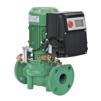
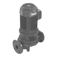
1.1 Application
The glanded design series IPL and DPL are preferable suited
for light industrial duties in:
– LTHW and MTHW heating systems
– Chilled water circulation systems
– Industrial heat transfer systems
– Process engineering
1.2 Description
1.2.1 Serial code
IPL 50/115 - 0,75/2 (N)
Inline flange
ended
Pump
DPL = Double Pump
ND pipe connections
Max. impeller size
Rated motor power
Motor polarity
IEC-standard motor / Stub shaft
ENGLISH
7
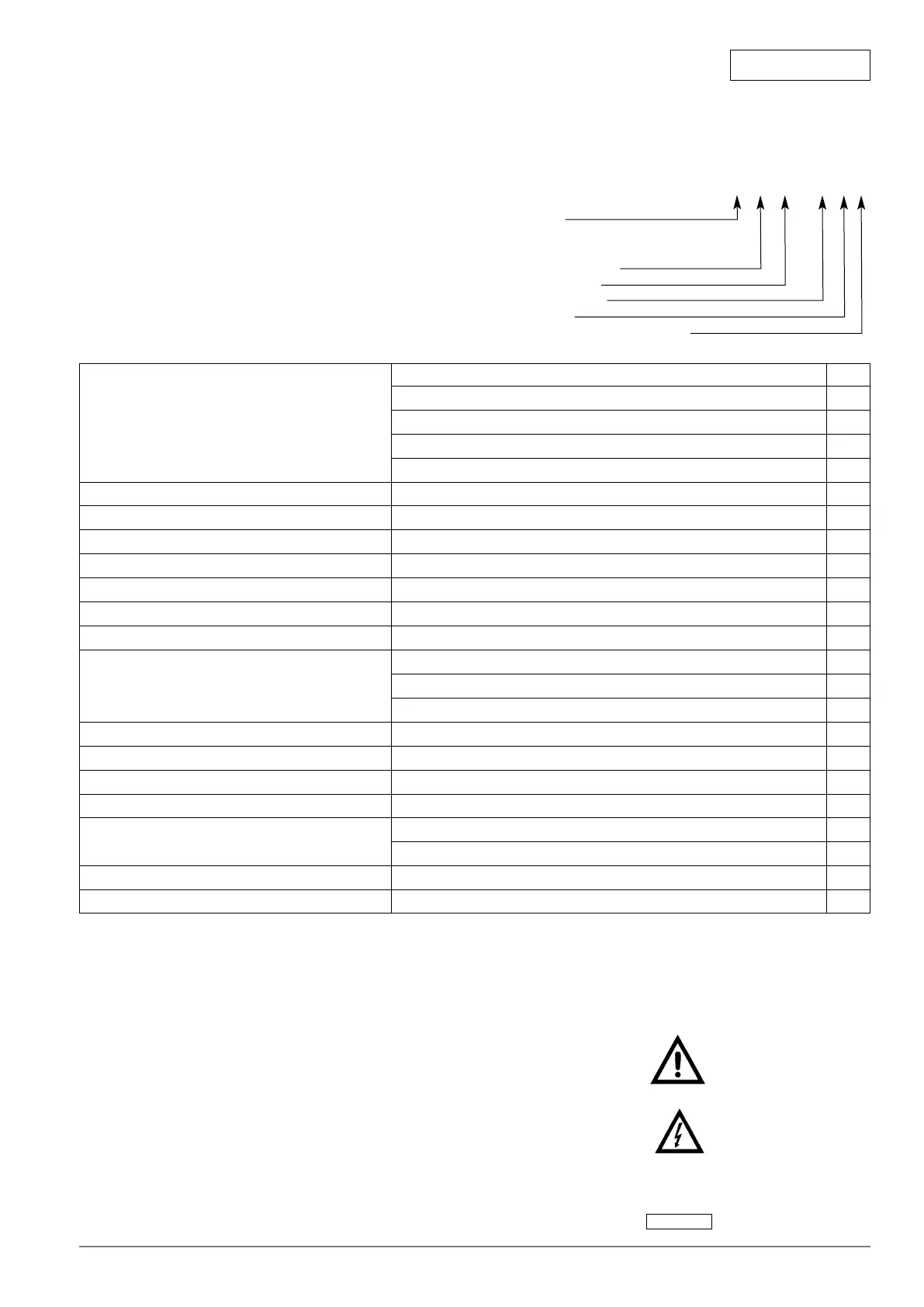
1.2.2 Technical data
Suitable fluids Hesting water to VDI 2035 x
Chilled/ Cold water x
Water/glycol mixtures
1
) X
Heat transfer oil X
Other fluids on request X
Permissible fluid temerature range from - 10°C to + 120°C x
max. working pressure 10 bar x
Installation method Inline x
Construction materialsPump housing EN-GJL-250 (formerly GG-25) x
Impeller F.R. polypropylene x
Stub shaft (N-version) Stainless steel X2 CrNiMo 1810 (1.4404) x
extended shaft Stainless steel X20 Cr 13 (1.4021) x
Pipe and gauge connections Flanges PN 16 / EN 1092-2 x
Flange with tappings 1/8“ x
all-purpose "combi" flanges PN 6/10 (H4) X
Mains power supply 3~400/415V, 50 Hz x
Degree of protection IP55 x
Motor protection On site by others x
Integrated protection WSK/KLF
2
) X
Variable speed drive Multi-speed motor X
Automatic controll gear (Wilo-CR/DR-systems)
3
) x
Special design motor Special voltage/frequency X
Pump Flame-/Explosion-proof (N-version) X
Legend:
x Standard supply
X Special design or accessories (at added cost on request)
1
) Water/glycol mixtures up to a ratio of 40% glycol and 40°C
maximum.
Allow for hydraulic corrections for glycol. Only approved
makes of additives with corrosion inhibitors must be used.
Observe manufacturers´instructions. Contact WILO before
using other than above listed fluids other ratio of mixtures
and higher temperatures.
2
) On- site trip unit required
3
) When used with respective WILO switch/control gear
When ordering spare parts, all data of pump and motor name
plate must be stated.
2. Safety
These instructions contain important information which must be
followed when installing and operating the pump. These ope-
rating instructions must therefore be read before assembly and
commissioning by the installer and the responsible operator.
Both the general safety instructions in the "Safety precautions"
section and those in subsequent sections indicated by danger
symbols should be carefully observed.
2.1 Danger symbols used in these operating instructions
Safety precautions in these operating instructions which, if not
followed, could cause personal injury are indicated by the sym-
bol:
,
when warning of electrical voltage with
The following symbol is used to indicate that by ignoring the re-
levant safety instructions, damage could be caused to the
pump/machinery and its functions:
ATTENTION!
 Loading...