en
8 Installation and operating instructions • Isar BOOST5 • Ed.06/2024-05
5
10
9 8 713 1112 6
15
14
9
1
4
3
2
10
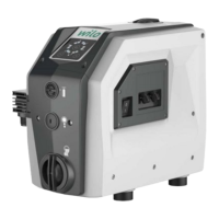
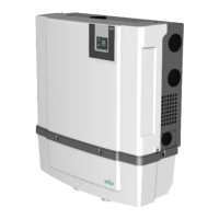
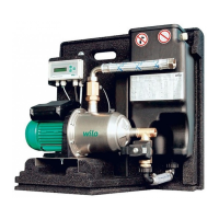
Fig.1: Product Overview
1 Refill opening cap
2 Extension card
3 Fuse (12.5A)
4 Input/Output cable entry
5 Main switch
6 Drainage screw plug
7 Venting screw
8 Diaphragm expansion tank closure
9 Discharge / suction port holder
10 Discharge / suction port handle grip
11 Pedestal (oscillation dampening)
12 Suction port
13 Mains cable
14 Discharge port
15 Control panel
2.2 Description of control panel
Fig.2: Control panel
1 LEDs: “Operating status”
• Pressure setting display
• Operation
• Fault or alarm
2 Operating buttons: “+” and “-”
3 Operating button: “On/Off”
4 LED: “System status” (green and red)