English
66 WILO SE 10/2013
• Install appropriate flat gaskets between pump and counter flanges.
• Tighten the flange bolts crosswise in two steps to the prescribed tightening
torque (see Table 7.1.2).
• Step 1: 0.5 x permissible tightening torque
• Step 2: 1.0 x permissible tightening torque
• Check the flange connections for leaks.
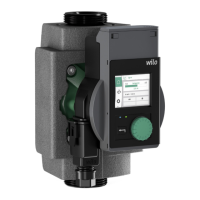
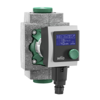
7.1.3 Insulation of the pump in heating systems
Fit the two half-shells of the thermal insulation before commissioning and push
them together so that the guide pins engage in the opposite holes.
WARNING! Risk of burns!
The entire pump can become very hot. When retrofitting the insulation dur-
ing normal operation there is a risk of burns.
7.1.4 Insulation of the pump in cooling/air-conditioning systems
• The thermal insulation shells (Fig. 5, item 1) included in the scope of delivery
may only be used in heating/drinking water circulation applications at fluid tem-
peratures of +20°C or higher, since these thermal insulation shells do not
enclose the pump housing in a diffusion-proof manner.
• For applications in cooling and air-conditioning systems, commercially-availa-
ble diffusion-proof thermal insulation materials must be used.
CAUTION! Risk of damage to property!
If the diffusion-proof insulation is fitted at the site, the pump housing may
only be insulated up to the motor flange. The condensate drain holes must
remain unobstructed to ensure that condensate that develops in the motor
can drain without problems (Fig. 6). Condensate that accumulates in the
motor can cause an electrical defect.
DN 80, 100 Nominal pressure PN6 Nominal pressure PN10/16
Screw diameter M16 M16
Strength class 4.6 or higher 4.6 or higher
Permitted tightening torque 95 Nm 95 Nm
Min. screw length for
• DN80 65 mm 65 mm
• DN100 70 mm 70 mm

 Loading...