Installation and electrical connection en
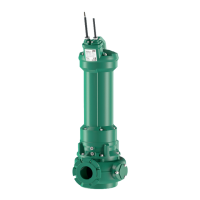
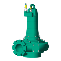
Installation and operating instructions Wilo Motor T 17.3, 20.2:, EMU FA, Rexa SUPRA, Rexa SOLID 71
connected to the pipe system on the suction and pressure side. Observe the following
points for installation:
ƒ The suction- and pressure-side pipe system must be self-supporting. The pump
must not support the pipe system.
ƒ Connect the pump to the pipe system ensuring that it is free of stress and vibrations.
The use of elastic connection pieces (compensators) is recommended.
ƒ The pump is not self-priming, in other words, the fluid must flow in either automati-
cally or with supply pressure. The minimum level in the collecting space must be at
the same height as the upper edge of the hydraulics housing!
ƒ Max. ambient temperature: 40°C (104°F)
Work steps
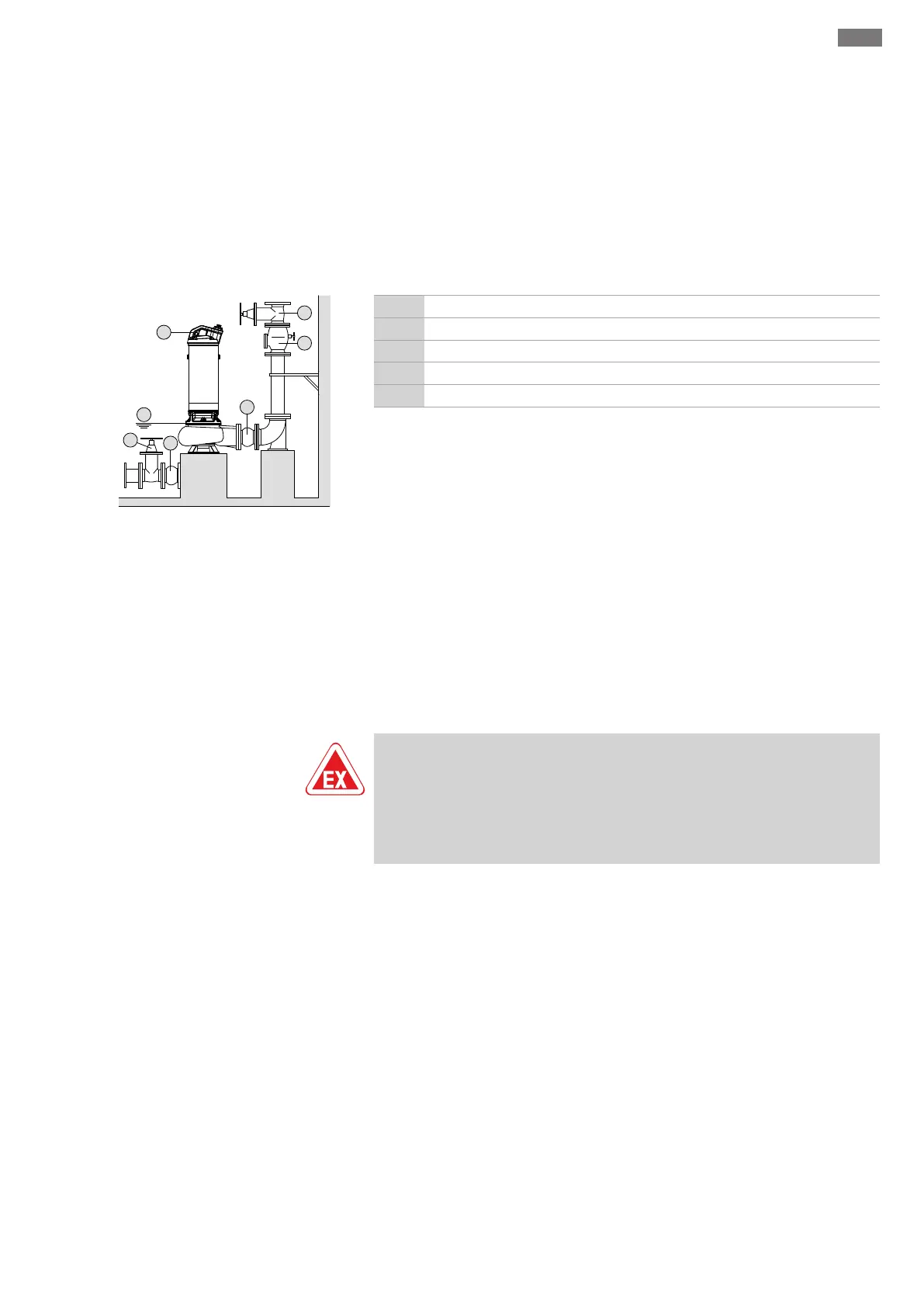
Fig.8: Dry well installation
1 Gate valve
2 Non-return valve
3 Compensator
4 Attachment point for lifting equipment
5 Minimum water level in collecting space
‡ Machine room/installation location is prepared for the installation.
‡ Pipe system has been properly installed and is self-supporting.
1. Use a shackle to attach the lifting equipment to the attachment point on the
pump.
2. Lift the pump and position it in the machine room. CAUTION!Hold the connection
cable slightly taut when positioning the pump!
3. Secure pump to the foundation properly.
4. Connect pump to the pipe system. NOTICE!Ensure the connection is free of
stress and vibrations. If required, use plastic connection pieces (compensators).
5. Loosen the lifting gear from the pump.
6. Have the connection cable installed in the machine room by a qualified electrician.
NOTICE!Do not damage the connection cable (no kinks, note the bend radius)!
▶ The pump is installed, the qualified electrician can make the electrical connection.
6.4.6 Level control
DANGER
Risk of explosion due to incorrect installation!
If the level control is installed within a potentially explosive area, the signal trans-
mitter must be connected via an Ex cut-off relay or a Zener barrier. There is a risk of
explosion if connected incorrectly! Connection must be carried out by a qualified
electrician.
With a level control device, the current fill levels are determined and the pump is
switched on and off automatically depending on the fill levels. Fill levels are recorded by
using different sensor types (float switches, pressure and ultrasound measurements or
electrodes). The following must be observed when using a level control device:
ƒ Float switches can move freely!
ƒ The water level must not fall below the minimum permissible!
ƒ The maximum switching frequency must not be exceeded!
ƒ If the fill levels fluctuate strongly, a level control with two measuring points is re-
commended. This makes it possible to achieve larger differential gaps.
6.4.7 Dry-running protection
Dry-running protection must prevent the pump from operating without fluid and air
from entering the hydraulics. The minimum permissible fill level must be determined
with the help of a signal transmitter. Once the specified limit value is reached, the pump
must be deactivated with an appropriate signal. Dry-running protection can expand the
available level controls by an additional measuring point or function as an independent
switch-off device. Depending on the system security, the pump can be restarted auto-
matically or manually. Installation of dry-running protection is recommended for op-
timum operational reliability.
 Loading...