12
OPM-171/B
To wire additional emergency stop switches first remove
the orange jumper between the two Emergency Stop
terminal blocks. Failure to remove the jumper will prevent
the remote switches from working properly. Add wires
between the terminal block to the new switch(s). The
switches must be wired in series for proper function. Test
each e-stop after wiring to ensure they function properly.
SERIAL COMMUNICATION
DSE provides a series of remote accessories that can help
provide useful information to operators. These accessories
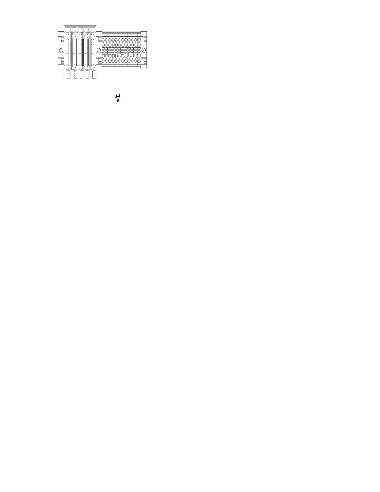
communicate over the DSE Net. Terminal blocks are wired
to the distribution panel to aid in installation. Follow the
instructions included with each accessory.
The generator controller can communicate with a variety
of controls and monitoring systems, including RS232 and
RS485. The ports are wired onto the back of the DSE7310.
In order to finalize communication the program will need
to be adjusted using the free DSE configuration software to
enable the communication. Contact Winco service for a list
of register values.
SCR (DSENET)
4A (DSENET)
4B (DSENET)
Battery Charge Fail
Emergency Stop
Emergency Stop
Remote Start +
Remote Start -
Ground
Ground
Battery +
Battery -
E-Stops