1. Intake filter
2. Intake valve
3. Control unit (electric)
4. Screw compressor
5. Separator tank with pre-separation
6. Fine separator
7. Minimum pressure valve
8. Oil thermostat
9. Oil filter
10. Oil cooler
11. Air after-cooler
12. Non-return valve
13. Safety valve
1.2
[en] 02/2014
Installation and operating manual - NK 31ROTORCOMP VERDICHTER
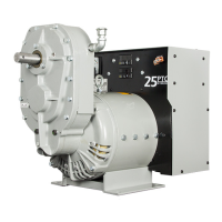
1.5.2 Purpose
The NK 31 is a screw compressor compact mod-
ule designed for installation in a compressed-air
generating station.
The sole intended use of the system is the
compression of atmospheric air. The NK 31 may
only be used to compress gases or other media
following written approval by ROTORCOMP.
The NK 31 may only be installed by specialized
companies with the corresponding know-how.
The safety precautions, technical data, limits, in-
stallation guidelines and regulations for commis-
sioning and operation specified in this operating
manual must be observed and complied with.
1.5.3 Standard delivery scope
With the NK 31, ROTORCOMP offers a com-
pletely equipped, compact compressor module.
The components of the standard delivery scope
are described in the following chapters.
Optionally available components are marked with
(optional).
1.6 Warranty information,
liability disclaimer
ROTORCOMP is a manufacturer of screw com-
pressor components and not of ready-to-operate
compressor systems.
RC shall only be answerable for any defects of
these individual components for which it is re-
sponsible within the scope of the warranty condi-
tions.
Failure to comply with the following instructions
and information shall void any and all liability.
This liability disclaimer also results in the loss of
claims for damages. This applies in particular in
case of:
– Installation not approved by RC
– Improper use
– Operation of the compressor outside the speci-
fied limits
– Failure to observe the safety precautions and
the usual care and caution
– Unsuitable operating materials (gases, oils)
– Condensate in the screw compressor
– Corrosion as subsequent damage
– Improper operation
– Insufficient maintenance, missing proof of
maintenance
– Use of unsuitable tools
– Failure to use genuine spare parts
– Unauthorized modifications to the screw com-
pressor module and/or its components–
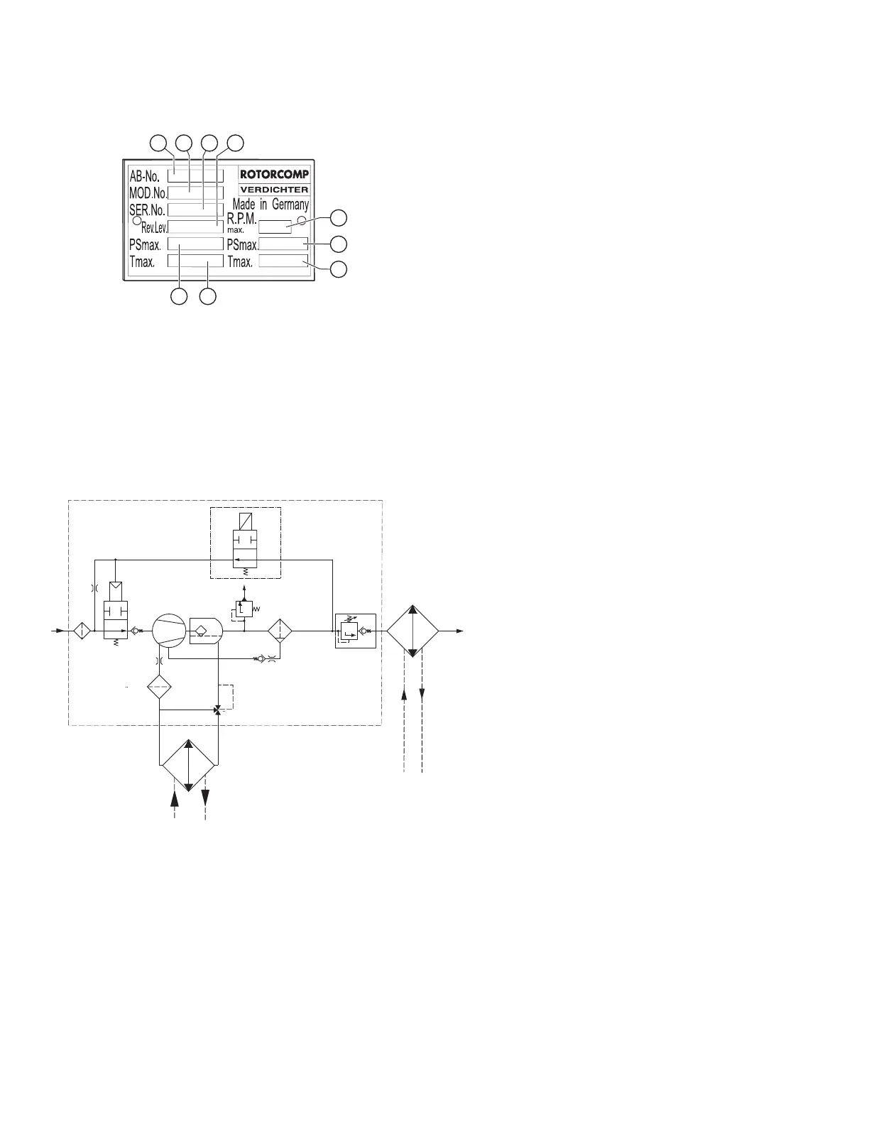
1.7 Nameplate
For the location of the nameplate, see Figure 3-1
or 3-3.
Should you have questions, please provide us
with the data on the nameplate. This ensures that
you receive the correct information.
Figure 1-1
Stamping for customers outside Germany
(Europe)
1. Order No.
2. Model
3. Serial No.
4. Year of manufacture
5. Max. rpm
6. Max. operating pressure in psi
7. Max. operating temperature °F
8. Max. operating temperature °C
9. Max. operating pressure in bar
Figure 3-2
3.2 Flow diagram of NK 31
(electric control unit)
3.3 Operating description for NK 31
Screw Compressor Compact Module
(electric)
The flow diagram shows a schematic view of the
operating principle and the arrangement of the
main components of the NK 31 screw compres-
sor module with electrical control unit, regardless
of any other equipment.
3.3.1 Standstill
At standstill the solenoid valve 3.1 is deener-
gized, the relief line is open and the downstream
devices are depressurized. The minimum pres-
sure valve 7 set to approx. 5.5 bar at the factory
is tightly closed. The intake valve 2 is slightly
open at standstill.