20
OPM-171/B
7. Refill with new oil at the filler neck to the maximum
level.
NOTE: The compressor must be operated with an oil
suitable for special requirements. This oil must be approved
by the manufacturer for screw compressors. It must even
be suitable under unfavorable operating conditions, such
as soiling of the intake air with gases, solvent vapors and
exhaust gases and at high ambient temperatures. Suitable
oil types and oil manufacturers can be specified for screw
compressor on request.
Refined oils (mineral oils) synthetic oils and bio oils
(biodegradable) can be used as screw compressor oil. The
materials and gaskets used in the screw compressor system
must be taken into account when selecting the oil type.
Corrosion and other material damage may not occur. It is
not permissible to mix different oils.
This compressor requires 101.4 ounces (3.17 quarts) of oil if
it is completely drained. Use caution when refilling.
8. Turn on the compressor and allow to run for 3 minutes.
9. Check oil level. Top off to the maximum level if needed.
CHANGING THE COMPRESSOR OIL
FILTER
WARNING: PERSONAL INJURY
Rotating, pressurized, and hot components. The oil
change can only be changed at a standstill and with the
compressor system completely discharged.
1. Switch off the
compressor and
disconnect the battery
to prevent the engine
from starting.
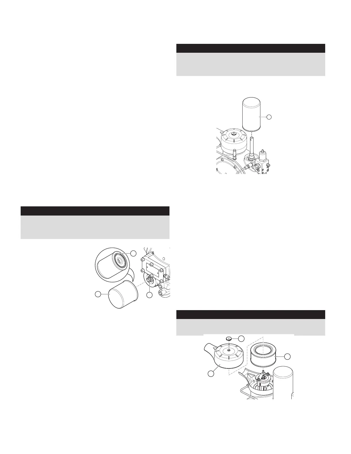
2. Remove the oil filter
cartridge (Ref. 1) with
a suitable tool, i.e. oil
filter strap wrench.
3. Oil the gasket (Ref. 2.) on the new filter cartridge with
the same oil type in use with the compressor.
4.Screw the new oil filter cartridge on (Ref. 3) and tighten
by hand.
5. Switch on the compressor.
6. Check the filter for leaks while the system is running.
7. Turn off compressor and check oil level. Top off to the
maximum level if needed.
7.4
[en] 02/2014
Installation and operating manual - NK 31ROTORCOMP VERDICHTER
7.3.3 Filling with oil
Attention
Observe the oil recommendation, see “Lubricants
and Operating Materials”. Add oil of the same oil
type from the same manufacturer.
Switching over to another oil type can require the
compressor module to be flushed.
ROTORCOMP recommends also replacing the
oil filter during an oil change.
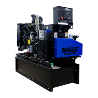
• Replace the oil filter if necessary
• Pour oil into the filler neck on the separator
tank up to the maximum level and screw the
screw plug 1 onto the filler neck by hand
(see Figure 7-2).
• Switch on the screw compressor and allow it to
run for approx. three minutes.
• Oil level check:
Top up the missing oil quantity again up to the
maximum level.
• Check sheet entry (see chapter 7.7 “Mainte-
nance check sheet”).
7.4 Oil filter
Warning
Rotating, pressurized and hot components,
DANGER OF INJURY
– The unit parts, oil and oil filler plug may be
over 80°C/176°F; danger of burns!
– Wear personal safety equipment!
The oil filter replacement may only be carried
out at a standstill and with the screw compressor
system completely discharged.
7.4.1 Oil filter replacement intervals
According to the specifications of the system
manufacturer.
For the reference values for the screw compres-
sor compact module, see chapter 7.8 “Mainte-
nance intervals”.
7.4.2 Oil filter replacement
Figure 7-3
• Switch off the system and completely release
the pressure in the system.
• Remove the oil filter cartridge 1 with a suitable
tool, e.g. oil filter strap wrench.
• Oil the gasket 2 on the new oil filter cartridge 1
with oil of the same oil type as in the compres-
sor module.
Note
Dispose of the old oil filter cartridge according to
the applicable regulations.
• Screw the new oil filter cartridge onto the con-
nection nipple 3 and tighten by hand. No tool is
required.
• Switch on the screw compressor.
• The oil filter must then be checked for leaks
with the system running.
• Oil level check:
Top up the missing oil quantity again up to the
maximum level.
• Check sheet entry (see chapter 7.7 “Mainte-
nance check sheet”).
1
2
3
REPLACING COMPRESSOR FINE
SEPARATOR CARTRIDGE
WARNING: PERSONAL INJURY
Rotating, pressurized, and hot components. The fine
separator cartridge can only be changed at a standstill
and with the compressor system completely discharged.
NOTE: Heavily soiled intake air or a poor oil quality will
result in early replacement of the fine separator cartridge.
1. Switch off the compressor and disconnect the battery
to prevent the engine from starting.
2. Unscrew the fine separator cartridge (Ref. 1) with a
suitable tool, i.e. an oil filter strap wrench.
3. Oil the gasket on the new fine separator cartridge with
the same oil type as in the compressor module.
4. Tighten the new fine separator cartridge by hand.
5. Switch on the system.
6. Check for any leaks.
REPLACING THE COMPRESSOR AIR
INTAKE FILTER
NOTE: The air filter must not be cleaned and then reused,
always replace the air filter.
WARNING: EQUIPMENT DAMAGE
No dirt or dust particles may get into the air inlet of the air
compressor.
1. Switch off the compressor and disconnect the battery
to prevent the engine from starting.
2. Screw off the nut (Ref 1) and remove the filter cover
(Ref. 2).
7.5
[en] 02/2014
Installation and operating manual - NK 31
7.5 Fine separator cartridge
Warning
Rotating, pressurized and hot components,
DANGER OF INJURY
– The unit parts and oil may be over 80°C/176°F;
danger of burns!
– Wear personal safety equipment!
The fine separator cartridge may only be re-
placed at a standstill and with the screw com-
pressor system completely discharged.
7.5.1 Maintenance intervals
According to the specifications of the system
manufacturer.
For the reference values for the screw compres-
sor compact module, see chapter 7.8 “Mainte-
nance intervals”.
With heavily soiled intake air or a poor oil quality,
the cartridge is heavily soiled, making premature
replacement necessary.
7.5.2 Replacing fine separator cartridge
Figure 7-4
Note
Dispose of the old fine separator cartridge ac-
cording to the applicable regulations.
• Unscrew the fine separator cartridge 1 with a
suitable tool, e.g. oil filter strap wrench.
• Oil the gasket on the new fine separator car-
tridge 1 with oil of the same oil type as in the
compressor module.
• Tighten the new fine separator cartridge by
hand. No tool is required.
• Switch on the screw compressor system.
• The fine separator must be checked for leaks
with the system running.
• Check sheet entry (see chapter 7.7 „Mainte-
nance check sheet“).
1
7.6
[en] 02/2014
Installation and operating manual - NK 31ROTORCOMP VERDICHTER
7.6 Intake air filter
7.6.1 Maintenance intervals
According to the specifications of the system
manufacturer.
For the reference values for the screw compres-
sor compact module, see chapter 7.8 „Mainte-
nance intervals“.
In case of heavily soiled intake air, an earlier
replacement of the filter element is necessary
when the optical or electric maintenance indica-
tor (optional) indicates this (perm. vacuum up to
50 mbar).
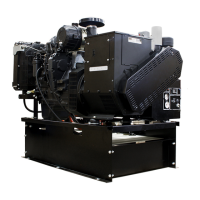
7.6.2 Replacing air filter element
Figure 7-5
Attention
No dirt or dust particles may get into the air inlet
of the screw compressor.
Note
It is not permissible to clean the filter element;
the filter element must always be replaced in
case of soiling!
Dispose of the old air filter element according to
the applicable regulations.
3
1
2
• Switch off the system and secure it against
unauthorized switch-on.
• Screw off the nut 1 and remove the filter
cover 2.
• Carefully remove dust from the filter housing.
• Remove the old filter element 3.
• Insert the new filter element in the filter hous-
ing.
• Lay on the filter cover, ensuring proper posi-
tioning during assembly.
• Tighten the wing nut.
• Switch on the screw compressor system.
• Conduct a test run and an operating test.