4
AMPLIFIED MODELS ONLY
STEP 10: Select location for wall plate. Run two coax
cables (three if set 2 jack is going to be used) (RG-59
type) between locations and install connectors on each
end. Mark cables so "cable input", "TV output" "Set
2" may be identified. Antenna downlead and +12 VDC
will also be needed at inside wall plate/power supply
location.
STEP 11: The wall plate/power supply assembly may
be flush mounted in most standard electrical boxes. To
flush mount cut a hole in wall to fit the box. Run 2 #12
wires between wall plate/power supply and +12 VDC
source and route downlead cable to this location.
CAUTION
THE POWER SUPPLY SHOULD BE TURNED OFF
WHEN CONNECTING CABLES/WIRES TO POWER
SUPPLY. SEE FIGURE 10.
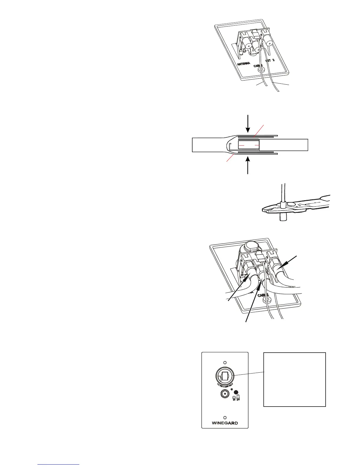
STEP 12: Make 12 volt connection to wall plate/power
supply Figure 6. Install terminals on wires from +12 VDC
source as shown in Figure 7. Crimp terminals with
Craftsman type 4 crimping tool or equivalent. See Figure
8. Push wires onto tabs on terminal board as shown in
Figure 6. If in doubt as to the polarity of the wires,
connect them temporarily to tabs on circuit board and
press ON switch on front of wall plate; if light comes on
polarity is correct. See Figure 10.
STEP 13: Install connectors on downlead, set 2 and
cable input cables as shown on page 6. Attach downlead
cable to jack on wall plate/power supply marked an-
tenna as shown in Figure 9. Attach cable going to set 2
outlet to jack on power supply marked SET 2. Attach
cable coming from cable input to jack on power supply
marked CABLE.
STEP 14: Mount power supply in wall with screws
provided and attach TV set cable to jack on front of
power supply/wall plate. Press ON switch on front of
wall plate and check that light is on. See Figure 10.
CHECKING OPERATION OF POWER SUPPLY
1. Tune TV receiver to nearest station and rotate antenna
for best picture and sound.
2. Press OFF switch on power supply. Picture on TV
should be considerably degraded with power off.
3. This unit is equipped with a polyswitch, (current
limiting device), which will shut down +12 VDC if there is
a direct short between antenna and power supply. Red
indicator light will not light. Once short is eliminated,
device will reset itself.
ADDING OPTIONAL AMPLIFIED WALLPLATE TO
NON-AMPLIFIED RV/TV INSTALLATION
The RA-7596 solid state TV signal amplifier works with
any non-amplified RV/TV antenna. Improves picture
quality. Uses +12 VDC. Has on/off switch, indicator light,
set 2 output, cable input and +12 VDC receptacle.
FIGURE 6
-12 VDC
(Ground)
+12 VDC
FIGURE 8
FIGURE 9
Cable Input
Set 2
Output
FIGURE 10
WARNING
DO NOT connect high
current devices such as
hair dryers to this
receptacle. Maximum
current rating of this
receptacle is 8 amps at
+12 VDC.
FIGURE 7
Connector
Ferrule
Crimp Here
1/4" #12 Wire
Remove 1/4" of insulation
from #12 wire.
Connector
Insulation
Antenna
Downlead
Rev. 10/99
 Loading...