23 - Technical data -
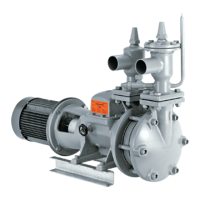
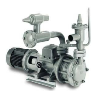
4.9 DESCRIPTION OF OPERATION
From the surge drum refrigerant liquid flows into the suc-tion chamber of the pump. A conical
filter is positioned in the suction connection. A special design of the suction chamber reduces
the inlet friction. The fluid pressure is increased by passing through one or two stage impellers
and intermediate piece(s).
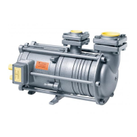
Due to the lateral channels in the intermediate pieces the pump can deliver a gas/liquid mixture
without surging or reversing the flow.
The special double shaft seal with associated oil reservoir in the between ensures that no
refrigerant will escape outside the system.
During standstill any gas that evaporates must be able to leave the pump and vent to the surge
drum. If the pump can be isolated on the delivery side or if a return valve is mounted, a purge
line with a diameter of 10 mm (0.4”) must be installed between delivery flange and stop valve
and connected to the wet suction return line.
The WITT stop/return valve ERA is provided with a purge connection pipe DN 10 and a hand
regulating valve EE6, supplied loose. The EE6 should be fitted so that any gas may be purged
to the surge drum. The valve should be left ½ - ¼-turn open depending on the differential
pressure (see also fig. 6).
4.10 PERFORMANCE CHARACTERISTIC TABLE
1450 1/min (RPM)
LIQUID
HEAD
[m]
PRESSURE DIFFERENCE [bar] VOLUME FLOW [m³/h]
NH
3
R 22
GP 41 GP 42 GP 51A GP 51 GP 52 GP 82
EVAPORATING TEMPERATURE t
0
+40°C -40°C +40°C -40°C
2 0,11 0,14 0,22 0,28 3,4 3,6 10,2 16,8 16,8 24
4 0,23 0,27 0,44 0,55 3,2 3,4 10 16,5 16,5 23,5
6 0,34 0,41 0,67 0,83 2,9 3,3 9,7 16,3 16,3 23
8 0,45 0,54 0,89 1,13 2,7 3,1 9,4 16,1 16,2 22,4
10 0,57 0,68 1,11 1,38 2,6 3 9 15,7 16,1 21,8
15 0,85 1,02 1,67 2,08 2,2 2,6 8,3 14,2 16 20,3
20 1,14 1,35 2,22 2,77 1,8 2,4 7,4 12,3 15,8 19
25 1,42 1,69 2,78 3,46 1,4 2,1 6,3 9,8 15,1 17,8
30 1,7 2,03 3,33 4,15 - 1,9 5,5 7 14,2 16,6
35 1,99 2,37 3,89 4,84 - 1,6 4,5 3,6 13,5 15,5
40 2,27 2,71 4,45 5,54 - 1,3 - 0 12,5 14,3
45 2,56 3,05 5 6,23 - 1,1 - - 11,1 13
50 2,84 3,38 5,56 6,92 - 0,8 - - 10,4 11,6
55 3,12 3,72 6,11 7,61 - - - - 9,3 10
60 3,41 4,06 6,67 8,31 - - - - 8 8,4
65 3,69 4,4 7,22 9 - - - - 6,5 -
70 3,98 4,74 7,78 9,69 - - - - 5 -
1 m = 3.281 ft | 1 bar = 14.504 PSI | 1 m³/h = 4.403 gal/min