- Applications - 26
RECIRCULATION RATES AND PUMP CAPACITY
Recirculation factor Recirculation flow in m³/hr per 100 kW*
Refrigerant CO
2
NH
3
R22 CO
2
NH
3
R22
Air Cooler 1,2 – 2,0
3 - 4 2 - 3 1,4 – 2,4 1,3 – 1,8 2,8 – 4,3
Plate Freezer
5 - 10 7 - 10 5 - 10 6 - 12 3 – 4,5 6,5 - 13
Liquid Chiller
1,2 – 1,5 1,2 – 1,5 1,2 – 1,5 1,4 – 1,6 0,6 1,7
*) including re-circulation rate
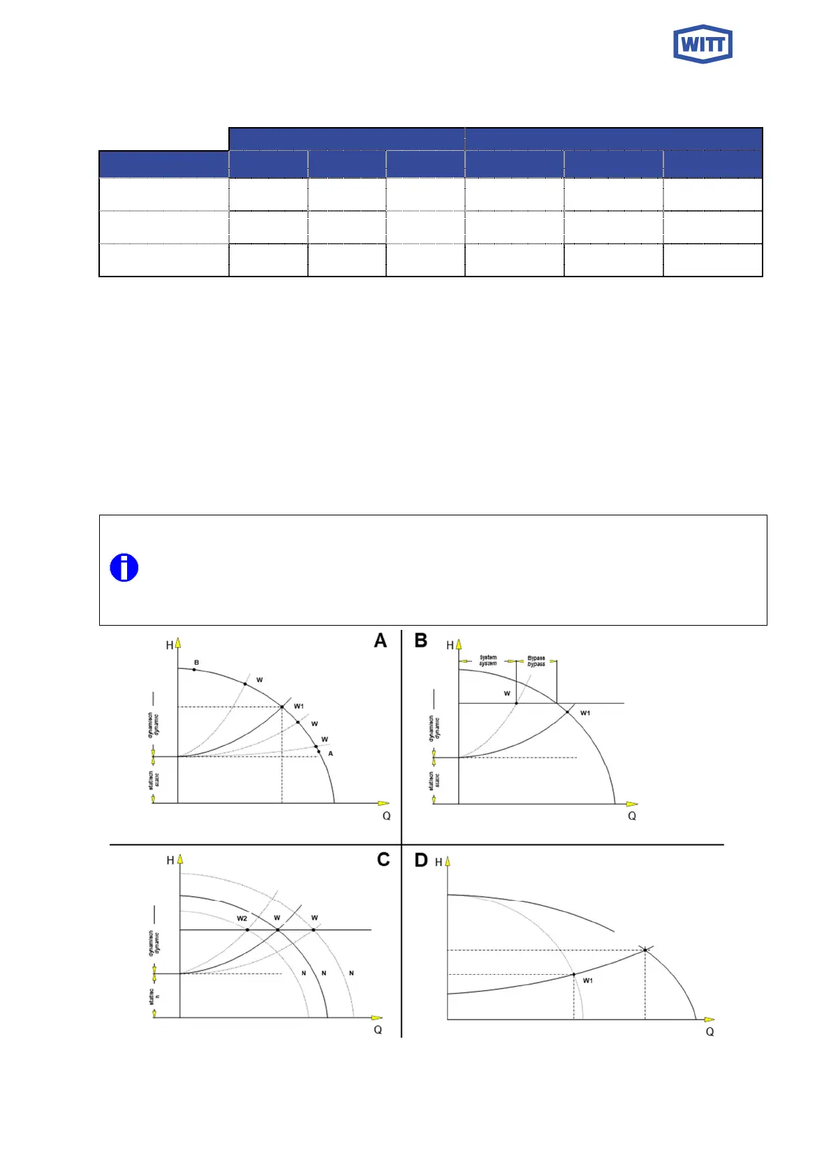
5.4 ADAPTATION TO PLANT REQUIREMENTS
Fig. 5 shows different plant operating conditions. The delivery head H is shown in relation to
the required plant capacity Q.
Performance curve characteristics of the refrigerant pump are shown in fig 5A. The different
points W mark the varying plant conditions that may occur during operation.
If the required liquid flow does not correspond with the available pump capacity then the liquid
flow to the sys-tem can be adjusted as follows:
pump capacity too large:
switch off a pump
open a liquid bypass valve, fig. 5B
speed control of the pump, fig 5C
pump capacity too small:
switch on an extra pump, fig 5D
install a larger pump
Fig. 5, A-D
V
1
+V
2
≠ 2 x V
1