- Installation requirements - 28
Do not connect two or more pumps in operation by a single common pump suction line liquid
header.
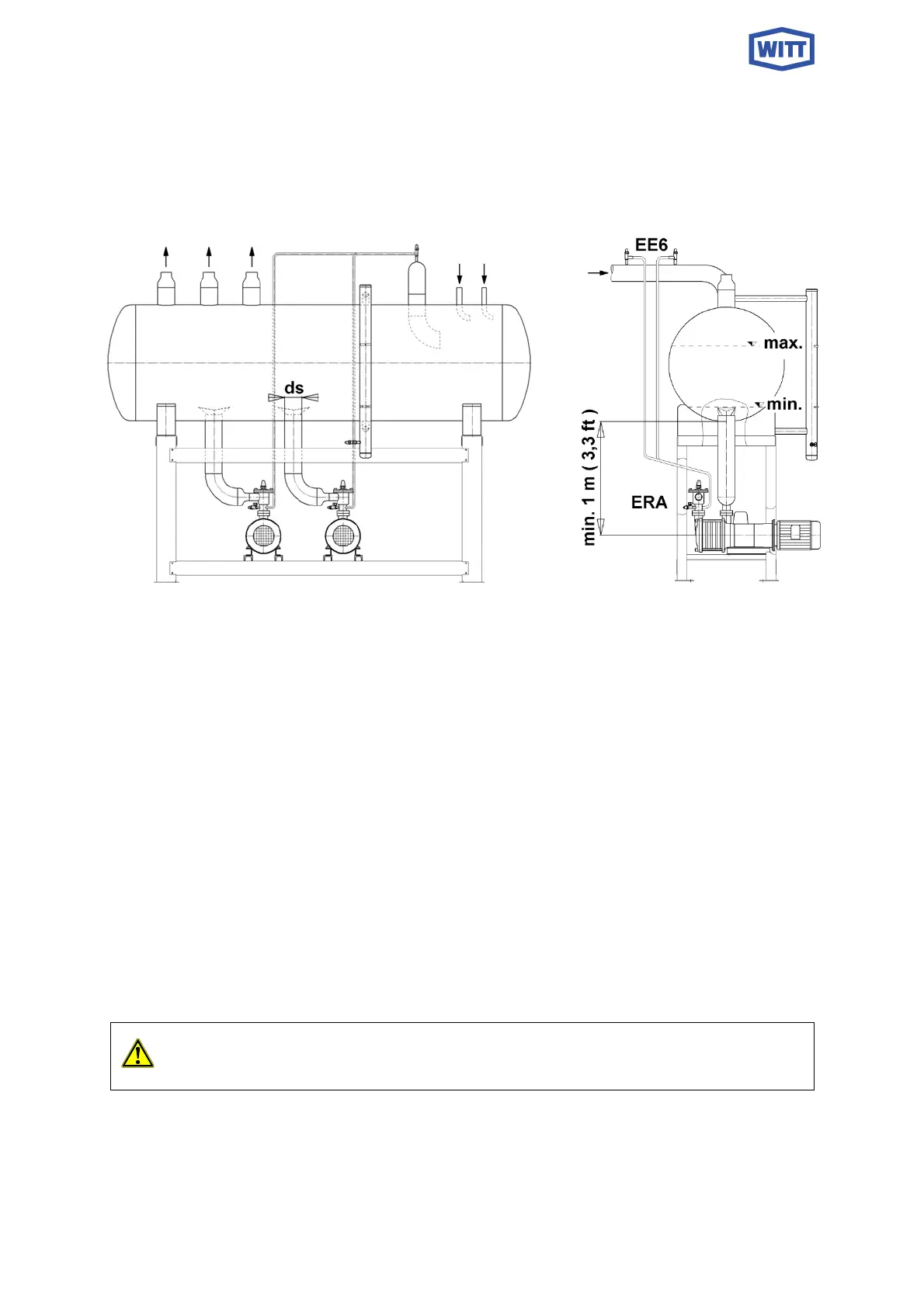
Fig.6 Application with two pumps in operation
6.3 DOWNLEG DESIGN
The pump shall be connected using a vertical pipeline to the separator. To prevent interaction
between pumps it is advised that each pump be connected individually to the separator, see
fig. 6.
Only when a stand-by pump is installed may two pumps be connected to a common downleg.
To avoid liquid vortexing the downleg should again pro-trudes into the separator and be fitted
with a vortex breaker.
An oil drainage dome around the down leg can be used to collect oil.
It is important that the vertical suction line is installed directly to the pump, avoiding additional
elbows or horizontal run.
Any gas accumulation in the suction line and particularly in valves attached to the pump must
be avoided. Gas bubbles should be able to flow back (counter flow) to the separator unhin-
dered, particularly when the pump is not in operation.
When there is no separate vent line installed it is important the pumps can vent to
the suction side, which means the suction downleg must be open during stand-still.