- Installation requirements - 30
6.4 PUMP DISCHARGE LINE
The sizing of the discharge line is less critical to the sys-tem operation. A liquid velocity of 1.5
m/s is normally recommended.
A non-return valve (this is usually a combined stop/check valve type ERA) in the
discharge line is required when a backwards flow from the discharge to the suction
side is possible. This may be the case, when:
several pumps are connected to one discharge manifold.
the static head to the coolers is high.
A non-return valve should be mounted as close as possible to the discharge flange. If a larger
distance is required, an additional vent line should be installed to prevent a possible gas block-
age.
Vent line
If the suction line needs to be closed during stand-still or the check valve is installed in a dis-
tance from the pump an additional vent line is required.
A minimum flow line is always recommended in CO
2
sytstems, which also vents the pump
during stand-still.
To avoid backflow of refrigerant during stand-still it is important that each pump is individually
connected with a separate vent line immediately in front of the check valve on the delivery side
to the top of the surge drum.
The stop valve after the orifice shall be DN20 (3/4”) respective DN25 (1”) if installed in the part
of the vent line that can contain liquid.
If the valve is installed in the gas part of the vent line, immediately in front of the connection
point to the vessel a smaller valve is sufficient, e.g. DN10 (0.4”). The stop valve must be locked
in an open position and marked “do not close during normal operation”.
In application with a non-return valve or solenoid valve liquid may be trapped. When
this liquid is warmed up, the pressure increases rapidly to an unacceptable value
and the piping may fracture.
Adequate precautions must be taken by the installer to prevent any liquid from becoming
trapped.
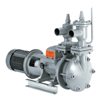
6.5 PROTECTION OF THE PUMP
GP refrigerant pumps with flanged motor are of a robust design and do not require special
protection besides with common motor protection switch.
The following protections provide additional safety.