Component Access and Removal
EElleeccttrriicc CCooookkttooppss
4-4
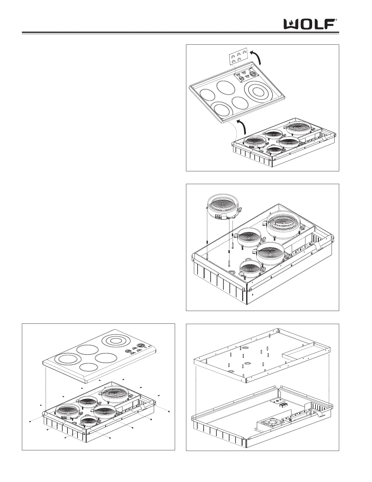
Figure 4-2. Glass Top Assembly Removal
Figure 4-3. Control Board Removal
Glass Top Assembly Removal
The cooktop will have to be removed from its installa-
tion in order to remove the glass top assembly.
NOTE: See page 4-3 for flushmount installation
removal.
Extract the screws that secure the glass top and trim to
the burner box. Next, carefully lift the glass top up until
access to the ribbon cable is obtained. Now, locate the
ribbon cable connector on the glass top, gently push
the tabs of the connector to the sides and lift the ribbon
cable from the connector and remove glass top assem-
bly. (See Figure 4-2).
Control Board Removal
Lay the glass top down so the control board points
upward. Now, push in the tabs which mount the control
board to the keypad board. Next, lift the control board
straight up and off of the tabs and remove.
(See Figure 4-3).
Surface Unit Removal
First, disconnect all the wiring to the surface unit. Now,
lift the surface unit straight up and off of the springs and
remove. (See Figure 4-4).
Inner Burner Box Removal
First, disconnect all wiring to the surface units. Then,
remove all surface units. Next, carefully lift the insula-
tion from the burner box and remove. Then, extract the
screws which secure the inner burner box to the burner
box assembly. Now, lift the inner burner box straight
up while pushing the wiring through inner burner box
and remove. (See Figure 4-5).
Figure 4-4. Surface Unit Removal
Figure 4-5. Inner Burner Box Removal
 Loading...