Installation Information
Gas Range (GR) Series
Gas Range (GR) Series
2-9
#822634 - Revision A - January, 2013
Placement
Do not lift or carry the oven door by the door handle.
The range has rear casters which allow for easy move-
ment by lifting the front of the unit.
Use an appliance dolly to move the unit near the open-
ing. Remove and recycle packing materials. Do not dis-
card the anti-tip bracket supplied with the range.
If a riser has been specified, refer to the installation
instructions packaged with the riser. The riser must be
installed before the range is installed.
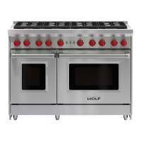
Anti-Tip Bracket
To ensure the anti-tip bolt engages the bracket, position
the bracket 3" (76) from the left side of the opening.
Refer to Figure 2-6.
Figure 2-6. Anti-Tip Bracket Location
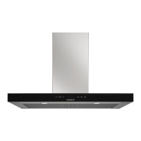
Anti-Tip Bracket Installation
Drywall Application
After properly positioning the anti-tip bracket, mark
holes, then use a Philips screwdriver or a low rpm
power drill to drive the wall anchor into the surface of
the wallboard until flush. Pre-drill holes if needed. For
hard wallboard or double-board construction, use a 1/4”
drill bit. For solid plaster, use a 7/16” drill bit. Refer to
Figure 2-7. Use #8 screws and flat washers to fasten
the bracket to the wall.
ANTI-TIP
BRACKET
WALL
ANCHOR
Figure 2-7. Anti-Tip Drywall Application
Wood Floor Application
After properly positioning the anti-tip bracket, drill 3/16”
(5) pilot holes through the floor. Use #12 screws and
flat washers to secure the bracket to the floor.
Concrete Floor Application
After properly positioning the anti-tip bracket, drill 3/8”
(10) holes into the concrete a minimum of 1-1/2’ (38)
deep. Use 3/8” wedge anchors to secure the bracket to
the floor.