EasyManua.ls Logo

Wolf 30 User Manual

Wolf 30
84 pages
To Next Page IconTo Next Page
Page #1 background imageLoading...
Page #1 background image
SERVICE MANUAL INTRODUCTION
This service manual helps with troubleshooting and diagnosing
malfunctions, completion of repairs, and return of the product to
proper operating condition. Read the complete instructions
contained within before initiating any repairs.
This guide is intended for use by Factory Certified Service. Wolf
Appliance, Inc. recommends that only Factory Certified Service
companies do repairs.
Warning and Caution product safety labels appear throughout
this manual. Product safety labels appear at the beginning of
some sections. Follow the instructions in the product safety
labels to avoid personal injury and/or product damage. The
sample safety labels explain the types of notices that appear in
this manual.
WARNING
States a hazard that may cause serious injury or
death if precautions are not followed.
CAUTION
Indicates minor injury or product damage may occur
if precautions are not followed.
IMPORTANT NOTE: Highlights especially important information.
TIP: Indicates additional, useful information.
Information and images contained herein are copyright of Wolf
Appliance, Inc. Neither this manual nor any information or
images contained herein may be copied or used in whole or in
part without the express written consent of Wolf Appliance, Inc.
©
Wolf Appliance, Inc., all rights reserved.
WOLF PRODUCT RATING PLATE INFORMATION
The Induction Range rating plate is located on the bottom of the
bullnose assembly.
Wolf Appliance, Inc.
Fitchburg, WI
9019151-002
INDUCTION RANGE
HOUSEHOLD COOKING APPLIANCE
Date Code
VOLTS : 220-240~ V kW: 14.4-16.0 kW
380-415 3N~ V 7.0-7.6 kW
Hz : 50/60 IPX0
MODEL #: ICBIR36550/S/TH SERIAL #: 17XXXXXX
Important information for each product is listed on the product
rating plate. Rating plates identify:
Model
Serial number
Electrical information
MODEL DESCRIPTIONS AND SALES ACCESSORIES
For more details on individual model descriptions and a listing
of all compatible sales accessories, see the
Wolf Product and
Sales Accessory Reference Guide
.
INDUCTION RANGE MODEL KEY
Model Character Description
IR Induction Range
30 or 36 Unit width
4 or 5 Number of induction burners
50 Model differentiator
/S Stainless steel
/T Tubular style handle
PRODUCT USE AND CARE AND INSTALLATION GUIDES
Product use and care guides, installation guides, and other
product specifications are available in the
Product
Specifications and Manuals Library
.
UNIT WARRANTY
Product warranty is determined by the installation location and
the date of installation.
View product warranties at
http://service.subzero.com/
ClaimsAndOrderProcessing/Pages/WarrantyInfo
.
Warranties start on the day of product installation.
Search for warranty and service information by serial
number, customer last name, and address using Unit
History at
http://service.subzero.com/Tools/UnitHistory
.
30" and 36" Induction Range
General Information
GENERAL INFORMATION
service.subzero.com
829191 REVA
1
Question and Answer IconNeed help?

Do you have a question about the Wolf 30 and is the answer not in the manual?

Wolf 30 Specifications

General IconGeneral
Width30 inches
Number of Burners4
ConvectionYes
Self-CleaningYes
Fuel TypeGas
Oven Capacity4.5 cu. ft.

Summary

General Information

SERVICE MANUAL INTRODUCTION

Introduction to the service manual for troubleshooting, diagnosing, and repairing the unit.

WOLF PRODUCT RATING PLATE INFORMATION

Details on identifying product model, serial number, and electrical information from the rating plate.

UNIT WARRANTY

Information on product warranty determination by installation location and date.

Settings

INITIAL POWER-UP SCREEN

Describes the screen sequence upon initial power-up or after a power loss.

SET THE LANGUAGE

Instructions for setting the unit's display language from available options.

Settings

SET THE TIME

Step-by-step guide to setting the current time and time format (12/24 hour).

Settings

SETTINGS

Overview of user-selectable preferences for the unit's settings.

Settings

SET SABBATH MODE

Instructions for enabling or disabling Sabbath mode on the unit.

Settings

SET THE CLOCK STYLE

Procedure to change the display style of the clock (analog, digital, etc.).

Settings

ENABLE THE CONNECTED FEATURE

Steps to enable or disable the unit's connectivity feature.

SET STANDBY

Instructions for configuring the standby mode settings.

Settings

CHANGE TEMPERATURE UNITS

Procedure to switch between imperial and metric measurement units.

Settings

About (Unit Information)

Accessing system information, model, serial number, and version details.

ADJUST TEMPERATURE OFFSET

How to adjust the oven's temperature offset by up to ±35°F.

Settings

CALIBRATE THE SCREEN

Procedure for calibrating the touchscreen for accurate input.

Settings

Adjust Volume and Tone

Guide to adjusting the volume and tone of beepers and chimes.

Settings

Adjust Brightness

Instructions for adjusting the display brightness level.

Cooking Modes

OVEN COOKING MODES

Overview of available oven cooking modes accessible via Quick Start or Gourmet.

BAKE MODE

Detailed steps for using the Bake cooking mode.

Cooking Modes

BROIL MODE

Instructions for operating the Broil cooking mode.

Cooking Modes

ROAST MODE

Detailed guide on using the Roast cooking mode.

CLEAN MODE

Procedure for activating the self-cleaning cycle.

Cooking Modes

WARM MODE

Instructions for using the Warm cooking mode.

Cooking Modes

CONVECTION ROAST MODE

Steps for operating the Convection Roast cooking mode.

Cooking Modes

CONVECTION MODE

Detailed instructions for the Convection cooking mode.

Cooking Modes

PROOF MODE

Guide to using the Proof cooking mode.

DEHYDRATE MODE

Instructions for operating the Dehydrate cooking mode.

Cooking Modes

STONE MODE

Detailed steps for using the Stone cooking mode.

Cooking Modes

GOURMET MODE

Instructions for navigating and using the Gourmet mode with recipes.

Cooking Modes

CONNECT MODE

Steps for connecting the appliance to the Sub-Zero Group Owner's App.

Auxiliary Controls

LOCK

How to lock or unlock the UIM (User Interface Module).

PROBE

Instructions for using the temperature probe for cooking.

Auxiliary Controls

TIMED COOK

Guide for setting and using timed cooking functions.

Auxiliary Controls

TIMER 1 AND TIMER 2

Instructions for operating Timer 1 and Timer 2 functions.

Auxiliary Controls

LIGHT

How to turn the oven light on or off.

Diagnostics

GENERAL DIAGNOSTICS

Accessing general diagnostic functions for unit inspection.

Diagnostics

Run Self-Test

Procedure to initiate and run the unit's self-test.

Change the Model

Instructions for changing the model configuration.

Diagnostics

Reposition the Screen

Steps to adjust the position of the display on the UIM.

Test Screen

Procedure for testing the UIM display for bad pixels.

Diagnostics

FAULTS

Accessing and viewing fault codes and names.

Diagnostics

STATISTICS

Viewing operational statistics like power cycles and operating time.

Diagnostics

SENSORS

Accessing and viewing data from various unit sensors.

Cooktop Controls

GLOBAL TOUCH PAD

Overview of the main cooktop touch pad functions.

CONTROL ZONE TOUCH PAD

Details on controlling individual cooktop zones and power levels.

USER OPTIONS MODE

Accessing advanced settings like volume, frequency, and auto-lock.

Cooktop Controls

Annunciator Volume Setting

How to adjust the volume of audio feedback.

Annunciator Frequency Setting

How to adjust the frequency of audio feedback.

Auto-Lock Setting

Configuration for the automatic cooktop lock feature.

Cooktop Controls

LED Brightness Setting

How to adjust the brightness of the control panel LEDs.

DIAGNOSTIC MODE

Accessing various diagnostic tests and readouts.

Generator Reconfiguration

Procedure to reconfigure the generator, clearing errors.

Cooktop Controls

Heat Sink Temperature Readout

Reading heat sink temperatures in Celsius.

Coil Temperature Readout

Reading coil temperatures in Celsius.

Cooktop Controls

Error Code Readout

Accessing and interpreting stored error codes.

Cooktop Controls

SOFTWARE VERSION INDICATOR

Displaying the software version of the unit's control.

Component Removal and Installation Sections

Unit Removal

Procedure for uninstalling the unit from its installation.

Unit Installation

Procedure for installing the unit into its location.

Cooktop Component Removal and Installation

COOKTOP REMOVAL

Steps to remove the cooktop assembly.

GLASS ASSEMBLY REMOVAL

Procedure for removing the glass assembly.

COOKTOP INSTALLATION

Steps for installing the cooktop assembly.

PRIMARY OR SECONDARY CONTROL BOARD REMOVAL

Procedure for removing the control boards.

Cooktop Component Removal and Installation

PRIMARY OR SECONDARY CONTROL BOARD INSTALLATION

Steps for installing the control boards.

COIL ASSEMBLY REMOVAL

Procedure for removing the coil assembly.

COIL ASSEMBLY INSTALLATION

Steps for installing the coil assembly.

Cooktop Component Removal and Installation

GENERATOR PLATE REMOVAL

Procedure for removing the generator plate.

GENERATOR PLATE INSTALLATION

Steps for installing the generator plate.

SWITCH MODE POWER SUPPLY REMOVAL

Procedure for removing the switch mode power supply.

Cooktop Component Removal and Installation

FAN ASSEMBLY REMOVAL

Procedure for removing the fan assembly.

GENERATOR ASSEMBLY REMOVAL

Procedure for removing the generator assembly.

Remove the Three-Burner or Four-Burner Generator Assembly

Specific steps for removing 3 or 4 burner generator assemblies.

Cooktop Component Removal and Installation

BULLNOSE REMOVAL

Procedure for removing the bullnose component.

BULLNOSE INSTALLATION

Steps for installing the bullnose component.

Electronic Component Removal and Installation

MOTOR DOOR LOCK REMOVAL

Procedure for removing the motor door lock assembly.

RELAY BOARD REMOVAL

Procedure for removing the relay board.

MOTOR DOOR LOCK INSTALLATION

Steps for installing the motor door lock assembly.

RELAY BOARD INSTALLATION

Steps for installing the relay board.

USER INTERFACE MODULE (UIM) REMOVAL

Procedure for removing the User Interface Module (UIM).

Electronic Component Removal and Installation

USER INTERFACE MODULE (UIM) INSTALLATION

Steps for installing the User Interface Module (UIM).

DISPLAY CONTROL ASSEMBLY REMOVAL

Procedure for removing the display control assembly.

Oven Door Component Removal and Installation

OVEN DOOR REMOVAL

Steps to remove the oven door.

OVEN DOOR INSTALLATION

Steps to install the oven door.

OVEN DOOR LINER REMOVAL

Procedure for removing the oven door liner.

Oven Door Component Removal and Installation

DOOR HANDLE REMOVAL

Steps to remove the oven door handle.

DOOR HANDLE INSTALLATION

Steps to install the oven door handle.

Cavity Component Removal and Installation

FOOT COVER REMOVAL

Procedure for removing the foot covers.

SKIRT REMOVAL

Steps to remove the skirt.

COVER COLLAR REMOVAL

Procedure for removing the cover collar.

Cavity Component Removal and Installation

EXHAUST DUCT REMOVAL

Procedure for removing the exhaust duct.

EXHAUST DUCT INSTALLATION

Steps for installing the exhaust duct.

HINGE REMOVAL

Procedure for removing the oven hinge.

Cavity Component Removal and Installation

GASKET REMOVAL

Procedure for removing the oven door gasket.

GASKET INSTALLATION

Steps for installing the oven door gasket.

DOOR SWITCH ASSEMBLY REMOVAL

Procedure for removing the door switch assembly.

Cavity Component Removal and Installation

INTAKE BAFFLE REMOVAL

Procedure for removing the intake baffle.

INTAKE BAFFLE INSTALLATION

Steps for installing the intake baffle.

OVEN BAFFLE REMOVAL

Procedure for removing the oven baffle.

Cavity Component Removal and Installation

CONVECTION FAN REMOVAL

Procedure for removing the convection fan.

CONVECTION FAN INSTALLATION

Steps for installing the convection fan.

Cavity Component Removal and Installation

CONVECTION ELEMENT REMOVAL

Procedure for removing the convection element.

BROIL ELEMENT REMOVAL

Procedure for removing the broil element.

CONVECTION ELEMENT INSTALLATION

Steps for installing the convection element.

BROIL ELEMENT INSTALLATION

Steps for installing the broil element.

BROIL ELEMENT PANEL REMOVAL

Procedure for removing the broil element panel.

Cavity Component Removal and Installation

SMOKE CATALYST REMOVAL

Procedure for removing the smoke catalyst.

SMOKE CATALYST INSTALLATION

Steps for installing the smoke catalyst.

BAKE TRAY ASSEMBLY REMOVAL

Procedure for removing the bake tray assembly.

Cavity Component Removal and Installation

BAKE TRAY ASSEMBLY INSTALLATION

Steps for installing the bake tray assembly.

Rear Component Removal and Installation

BACK PLATE REMOVAL

Procedure for removing the back plate.

BACK PLATE INSTALLATION

Steps for installing the back plate.

COOLING FAN REMOVAL

Procedure for removing the cooling fan.

COOLING FAN INSTALLATION

Steps for installing the cooling fan.

Rear Component Removal and Installation

THERMAL CUTOUT (TCO) REMOVAL

Procedure for removing the thermal cutout (TCO).

THERMAL CUTOUT (TCO) INSTALLATION

Steps for installing the thermal cutout (TCO).

Troubleshooting

TROUBLESHOOTING GUIDE

Guide to understanding error codes and their priorities.

Troubleshooting

INDUCTION RANGE ERROR CODES

Table listing error codes, components, descriptions, and service instructions.

Troubleshooting

INDUCTION COOKTOP ERROR CODES

Table listing cooktop-specific error codes and service instructions.

Technical Data

INDUCTION RANGE TECHNICAL DATA

General technical specifications for the induction range.

Technical Data

36" COOKTOP POWER LEVELS

Detailed power level settings for the 36" cooktop.

Technical Data

INDUCTION RANGE OVEN RATING CHART

Component ratings including voltage, amperage, watts, and ohms.

Wiring Diagrams

INDUCTION RANGE WIRING DIAGRAMS

Overview of wiring diagrams for the induction range.

Wiring Diagrams

WIRING DIAGRAM (IR30450 Cooktop)

Detailed wiring diagram for the IR30450 cooktop model.

Wiring Diagrams

WIRING DIAGRAM (IR36550/ICBIR36550 Cooktop)

Detailed wiring diagram for the IR36550/ICBIR36550 cooktop models.
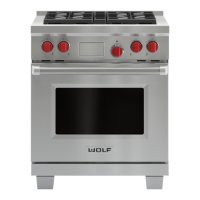
Related product manuals