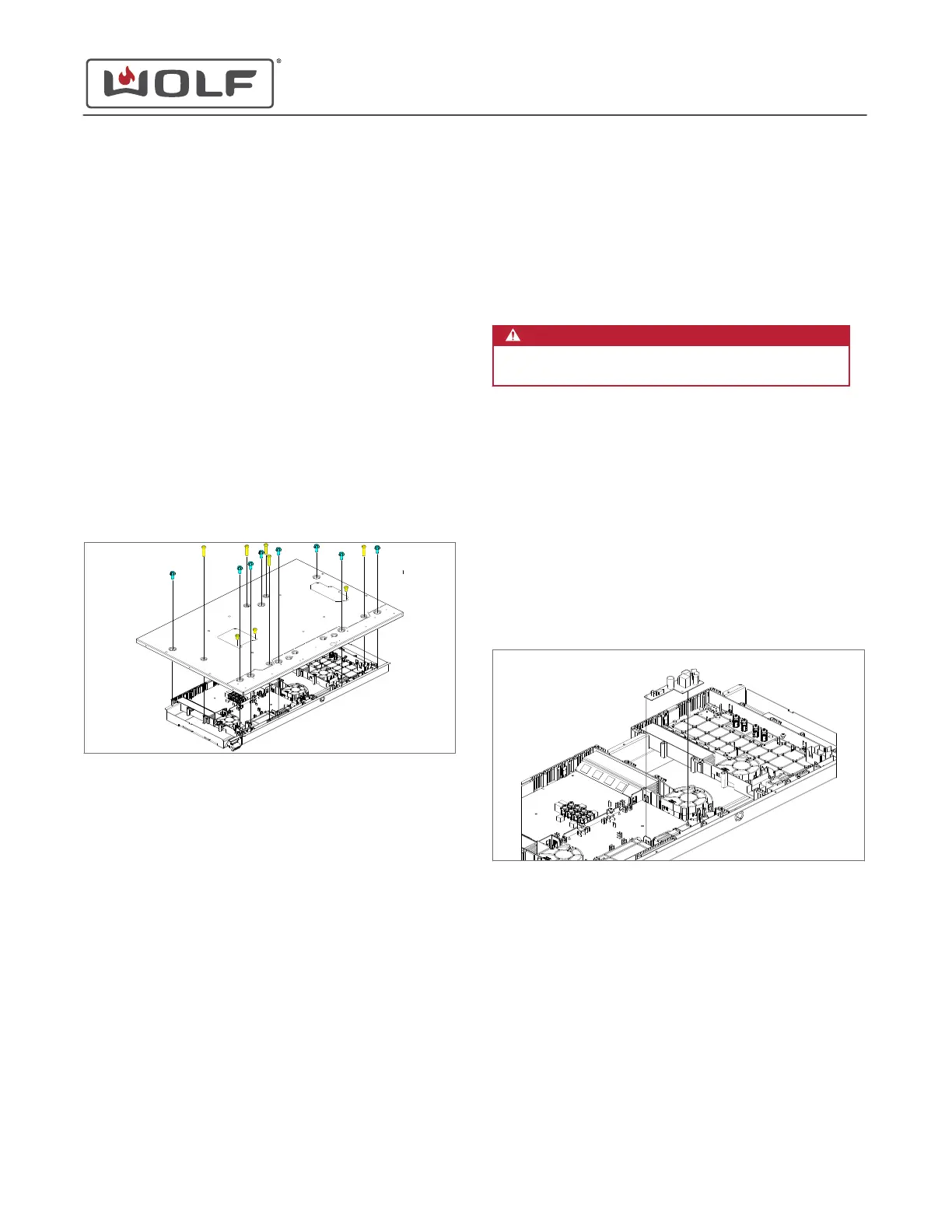
GENERATOR PLATE REMOVAL
To remove the generator plate, first
uninstall the unit
. Then
remove:
1
Cooktop
2
Glass assembly
3
Coil assembly
Remove the Generator Plate
1 Use a T-20 Torx bit to remove the screws that mount the
generator plate to the generator support.
2 Use a T-15 Torx bit to remove the screws that mount the
generator plate to the generator.
3 Use a T-15 Torx bit to remove the ground screw from the
coil wire connector opening.
4 Disconnect the two wire harnesses from the primary control
board.
5 Remove the generator plate from the generator support.
GENERATOR PLATE INSTALLATION
After installing the generator plate, install:
1
Coil assembly
2
Glass assembly
3
Cooktop
Then
install the unit
.
Install the Generator Plate
1 Place the generator plate onto the generator support.
2 Connect the two wire harnesses to the primary control
board.
3 Use a T-15 Torx bit to start the screws that mount the
generator plate to the generator.
4 Use a T-20 Torx bit to start the screws that mount the
generator plate to the generator support.
5
Use a T-15 Torx bit to install the ground screw into the coil
wire connector opening.
6 Use a T-15 and T-20 Torx bit to tighten all screws.
SWITCH MODE POWER SUPPLY REMOVAL
WARNING
Disconnect the product from the power source
before starting this procedure.
To remove the switch mode power supply, first
uninstall the unit
.
Then remove:
1
Cooktop
2
Glass assembly
3
Coil assembly
4
Generator plate
Remove the Switch Mode Power Supply
1 Disconnect the wire connectors and wire harness from the
switch mode power supply.
2 Remove the switch mode power supply from the board
supports.
SWITCH MODE POWER SUPPLY INSTALLATION
After installing the switch mode power supply, install:
1
Generator plate
2
Coil assembly
3
Glass assembly
4
Cooktop
Then
install the unit
.
30" and 36" Induction Range
Cooktop Component Removal and Installation
Generator Plate Removal (continued)
service.subzero.com
829191 REVA
48