Do you have a question about the Wolf Induction Range Series and is the answer not in the manual?
Steps to detach the base skirt shield from the appliance.
How to adjust oven door height using an Allen wrench.
Procedure to remove the oven door using a hinge pin.
Detaching the outer door skin from the liner assembly.
Removing oven door hinges attached to the liner assembly.
Extracting the oven's glass pack and insulation.
Detaching the oven door handle bar from standoffs.
Removing the oven door gasket using spring pins.
Steps to remove oven racks from sliding rails.
Detaching rack guides from shoulder screws.
Replacing halogen bulbs inside the oven cavity.
Removing the convection baffle attached to the back wall.
Detaching the convection element surrounding the fan.
Removing the convection fan from the oven's back wall.
Detaching the temperature sensor from the back wall.
Removing the smoke catalyst located in the oven cavity.
Removing the probe cover on the oven cavity side.
Detaching the broil element and deflector pan.
Removing the bake element from its tray assembly.
Detaching the induction cooktop from the range.
Removing the front bullnose trim from the unit.
Alternative method to remove bullnose using a suction cup.
Detaching the side panels and oven trim.
Removing the probe switch behind the side panel.
Removing halogen lamp located behind the inner side panel.
Detaching the back panel covering internal connections.
Removing the Thermal Cut Out (TCO) from the back unit.
Removing the cooling fan from its bracket.
Removing the terminal block from the back of the unit.
Detaching the glass top after removing the cooktop.
Removing the control board from its supports.
Removing a coil assembly from the generator plate.
Detaching the generator plate from the generator.
Removing the communication harness from the generator.
Removing the fan assembly from the generator plate.
Procedure to remove the IR304 generator assembly.
Procedure to remove the IR365 generator assembly.
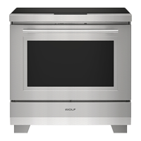
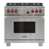
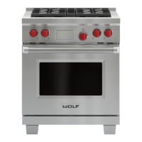
The Wolf Induction Range (IR) Series is a sophisticated cooking appliance designed for modern kitchens, combining an induction cooktop with a Dual Fuel oven. This manual provides comprehensive instructions for the removal and reassembly of various components, ensuring proper maintenance and servicing of the unit.
The Wolf Induction Range serves as a primary cooking appliance, offering both precise induction cooking on its cooktop and versatile baking/roasting capabilities in its Dual Fuel oven. The induction cooktop utilizes electromagnetic fields to directly heat cookware, providing rapid and efficient cooking with precise temperature control. The Dual Fuel oven combines the consistent heat of electric baking with the intense heat of a gas broiler, offering a wide range of cooking options. The appliance is designed for seamless integration into kitchen installations, with a focus on user convenience and operational safety.
The appliance features a robust design with several user-friendly components. The oven door, for instance, is designed for easy adjustment and removal. Its adjustment posts at the bottom allow users to raise or lower either side of the door, ensuring proper alignment with the bullnose. The door also incorporates a spring and damper system, with one hinge arm being spring-loaded, which facilitates smooth operation and controlled closure. For cleaning or servicing, the oven door can be fully opened, a hinge pin inserted into the spring-loaded hinge, and then lifted away from the unit at a 60-degree angle.
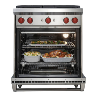
The oven interior is equipped with three types of racks: flat racks for any position, bent racks for the lowest position and easy pull-out onto the door, and sliding racks that glide on rails. These racks can be easily removed by pulling them forward until they stop, then lifting the front and pulling them out of the oven. The rack guides, which support the racks, can also be removed by lifting them up, pulling them toward the center of the oven to disengage from shoulder screws, and then pulling them forward.
Illumination within the oven cavity is provided by two halogen lamps, covered by pressed-on glass lenses. These bulbs can be replaced by first removing the adjacent rack guide, then using a flat-bladed screwdriver to remove the glass lens, and finally, using a clean, dry, oil-free cloth to handle the new bulb.
The convection system, crucial for even heat distribution, includes a convection baffle that covers the fans and elements. This baffle is attached to the back wall with screws and can be removed after the rack guides are taken out. The convection element, which surrounds the convection fan, is held by three screws and can be tilted up to disconnect spade terminals and wires, allowing for its removal. The convection fans themselves are secured to the back wall with multiple screws, ensuring they cannot be reversed during installation.
For precise temperature monitoring, the oven includes a temperature sensor attached to the back wall. This sensor can be accessed and removed by first taking out the oven racks, extracting its screws, pulling it into the oven cavity, and then disconnecting its wire harness. A smoke catalyst, located at the top of the oven cavity, helps manage cooking odors and can be removed by extracting its screws after the oven racks are taken out.
The appliance also features a probe cover on the right-hand side of the oven cavity, which can be removed by lifting it and using a 5/8" box wrench to remove its retaining nut. The broil element and its deflector are attached to the ceiling of the oven cavity and can be removed by extracting screws, pulling them forward to disconnect electrical connectors, and then separating them. The bake element, accessed from the front of the unit, sits in a tray that lowers down for removal. This involves removing the unit skirt, extracting screws from the tray assembly, lowering the front of the tray, disconnecting spade terminals with needle-nose pliers, and then lifting and pulling the bake pan assembly forward.
The induction cooktop, which sits atop the Dual Fuel oven, is designed for removal to access internal components. This process typically requires pulling the entire unit from its installation. Once the unit is accessible, the cooktop can be removed by extracting screws from the island trim and the rear of the cooktop, then lifting it from the rear to disengage it from keyhole slots on the bullnose, and finally disconnecting its electrical connection.
The bullnose, a decorative and functional component, can be removed after the cooktop. This involves opening the oven door, extracting screws below the bullnose, lifting it straight up to disengage from shoulder screws, and disconnecting the Control to ECH harness. An alternate method for bullnose removal, which avoids pulling the unit from installation, involves using a suction cup on the induction cooktop to lift it slightly, allowing the bullnose to be disengaged from shoulder screws and the face of the unit.
Side panels, which support the induction cooktop, are attached to the front and back of the unit. Their removal requires first taking off the induction cooktop and bullnose, then extracting screws from both the rear and front of the side panel and oven trim. Behind the right-hand side panel is the probe switch, which can be removed after the side panel is off, by removing the probe cover from the oven interior, extracting a screw from the meat probe access cover, pulling the switch from insulation, and disconnecting its electrical leads.
The halogen lamp located behind the inner side panel can be removed by first taking off the side panel, then extracting screws from the inner side panel, removing the inner side panel and insulation, and disconnecting the electrical connector. The back panel, covering various electrical connections, the Thermal Cutout (TCO), and cooling fan connections, can be removed by extracting screws from the island trim and the back panel itself.
The TCO, located on the back of the unit, can be reset by removing the left convection fan, but its replacement requires accessing the back of the unit. After removing the back panel, the TCO can be removed by disconnecting its electrical wires and extracting its screws. The cooling fan, situated behind a support bracket on the back of the unit, can be removed by first taking off the back panel, extracting screws from the fan motor bracket, pushing the bracket down, rotating the fan down while pulling it out, and disconnecting its electrical wires.
The terminal block, also on the back of the unit, is where the unit connects to power. Its replacement necessitates pulling the unit from installation. After removing the back panel, the terminal block can be removed by disconnecting its wires and extracting its holding screws. The induction cooktop wiring harness, which includes a noise filter, is connected directly to the terminal block and is separate from the main unit wiring harness.
The glass top of the induction cooktop can be removed after the cooktop itself is taken off the range. This involves using a small flat-bladed screwdriver or putty knife to remove the center of plastic rivets, then removing both rivets, extracting shoulder screws from the front frame with a Phillips screwdriver, and screws from the sides and back with a T-20 Torx bit. The control board, located beneath the glass top, can be removed by using needle-nose pliers to compress its support, lifting it off, and repeating for all supports, then disconnecting the comm cable.
Coil assemblies, part of the induction system, can be removed after the glass top. This involves using a small flat-bladed screwdriver to lift the coil assembly from the wire side, loosening screws holding coil assembly wires with a T-25, large Phillips, or large flat-bladed screwdriver, disconnecting the Negative Temperature Coefficient (NTC) sensor cable, and lifting the coil assembly off hook and loop fastener tabs. The generator plate, which houses the coil assemblies, can be removed after the comm harness is disconnected and the coil assemblies are taken out, by extracting ground screws with a Phillips screwdriver and screws holding the generator plate to the generator with a T-15, then feeding the comm harness through the plate. The comm harness itself can be removed by pushing a tab away from its connector on the generator.
Finally, the fan assembly, which cools the generator, can be removed after the generator plate. This involves pressing a connector tab, disconnecting the fan assembly connector, using a small flat-bladed screwdriver to spread retainer tabs, and then removing the assembly. The generator assembly (IR304 or IR365 models) can be removed after the generator plate. For the IR304, this involves turning the generator over, using a T-20 or large flat-bladed screwdriver to disconnect the power wire harness, and disconnecting the comm cable. For the IR365, additional steps include removing a wire clamp with a T-15, disconnecting connecting wire spade terminals, disconnecting the connecting ribbon cable, and disconnecting the comm cable.
The design of the Wolf Induction Range emphasizes ease of maintenance and component replacement. The detailed instructions for component removal are crucial for technicians to diagnose issues, replace faulty parts, and perform routine servicing. For instance, the ability to remove the oven door, racks, and rack guides simplifies cleaning the oven interior. The accessible halogen bulbs allow for quick replacement when they burn out.
The modular design of the convection system, with removable baffle, element, and fans, facilitates cleaning and replacement of these critical components, ensuring optimal oven performance. Similarly, the accessible temperature sensor and smoke catalyst allow for their inspection and replacement if they malfunction.
The design also considers the need to access internal electrical and control components. The clear steps for removing the induction cooktop, bullnose, side panels, and back panel provide a pathway to the wiring harnesses, terminal block, TCO, and other electrical parts. The inclusion of a noise filter on the induction cooktop wiring harness highlights attention to electrical integrity and performance.
The ability to remove the glass top, control board, coil assemblies, generator plate, and fan assembly on the induction cooktop side ensures that any issues with the induction heating system can be addressed efficiently. The specific instructions for different generator models (IR304 and IR365) demonstrate a tailored approach to maintenance, acknowledging variations in design.
Overall, the Wolf Induction Range is engineered with a strong focus on serviceability, providing clear, step-by-step procedures for component removal that enable effective troubleshooting, repair, and long-term maintenance of the appliance. The warnings and cautions regarding electrical shock, hot surfaces, and sharp edges underscore the importance of safety during any maintenance operation, recommending that only certified service technicians or installers perform complex procedures.
| Fuel Type | Electric |
|---|---|
| Convection | Yes |
| Self-Cleaning | Yes |
| Induction Zones | 4 |
| Control Type | Touch |
| Width Options | 30 inches |
| Burners | 4 |
| Voltage | 240V |
| Safety Features | Child lock |