Production Data WM8804
w
PD Rev 4.1 September 2007
23
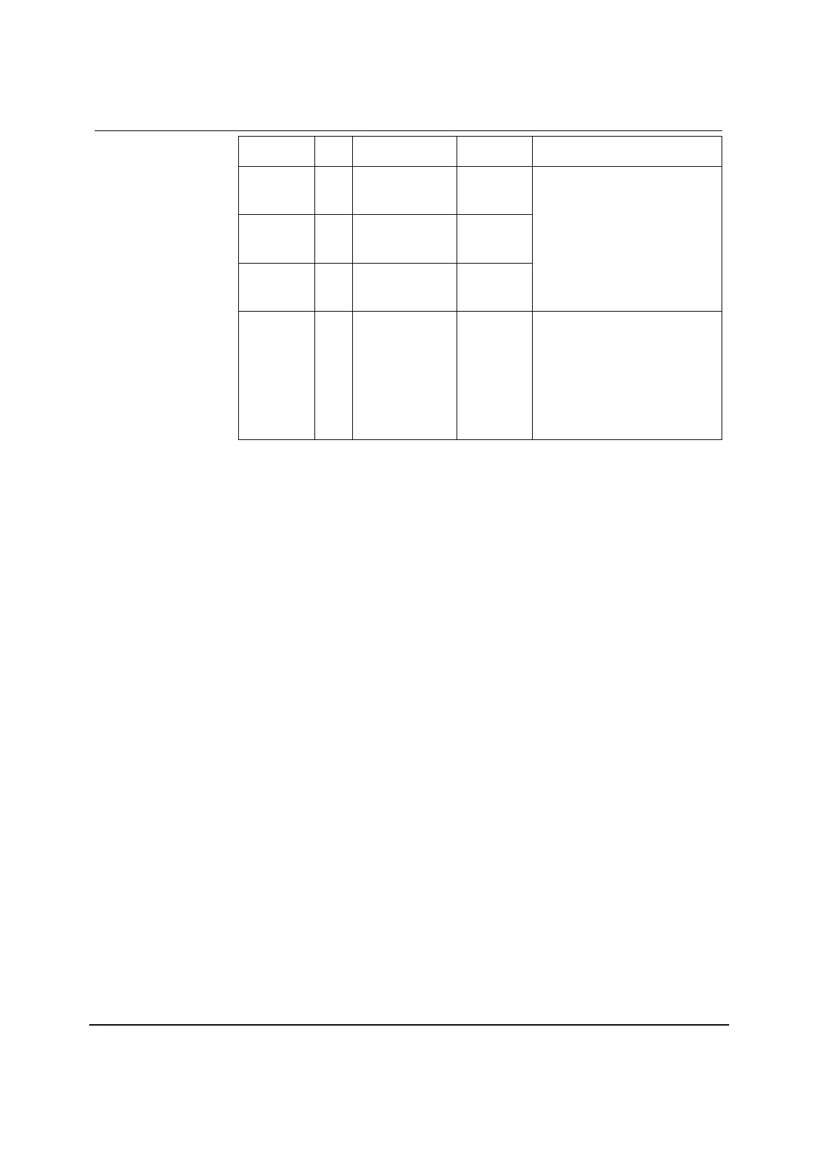
REGISTER
ADDRESS
BIT LABEL DEFAULT DESCRIPTION
R3
PLL1
03h
7:0 PLL_K[7:0] 00100001
R4
PLL2
04h
7:0 PLL_K[15:8] 11111101
R5
PLL3
05h
5:0 PLL_K[21:16] 00110110
Fractional (K) part of PLL frequency
ratio (R).
Value K is one 22-digit binary
number spread over registers R3,
R4 and R5 as shown.
Note: PLL_K must be set to
specific values when the S/PDIF
receiver is used. Refer to S/PDIF
Receiver clocking section for
details.
R6
PLL4
06h
3:0 PLL_N[3:0] 0111 Integer (N) part of PLL frequency
ratio (R).
Use values in the range 5 ≤ PLL_N
≤ 13 as close as possible to 8
Note: PLL_N must be set to
specific values when the S/PDIF
receiver is used. Refer to S/PDIF
Receiver clocking section for
details.
Table 21 User Mode PLL_K and PLL_N Multiplier Control
PLL CONFIGURATION
The PLL performs a configurable frequency multiplication of the input clock signal (f
1
). The
multiplication factor of the PLL (denoted by ‘R’) is variable and is defined by the relationship: R = (f
2
÷
f
1
).
The multiplication factor is set using register bits PLL_N and PLL_K (refer to Table 21). The
multiplication effect of both the N and K multipliers are additive (i.e. if N is configured to provide a
multiplication factor of 8 and K is configured to provide a multiplication factor of 0.192, the overall
multiplication factor is 8 + 0.192 = 8.192).
In order to choose and configure the correct values for PLL_N and PLL_K, multiplication factor R
must first be calculated. Once value R is calculated, the value of PLL_N is the integer (whole
number) value of R, ignoring all digits to the right of the decimal point. For example, if R is calculated
to be 8.196523, PLL_N is simply 8.
Once PLL_N is calculated, the PLL_K value is simply the integer value of (2
22
(R-PLL_N)). For
example, if R is 8.196523 and PLL_N is 8, PLL_K is therefore (2
22
(8.196523-8)), which is 824277
(ignoring all digits to the right of the decimal point).
Note: The PLL is designed to operate with best performance (shortest lock time and optimum
stability) when f
2
is between 90 and 100MHz and PLL_N is 8. However, acceptable PLL_N values lie
in the range 5 ≤ PLL_N ≤ 13. Do not use values outwith this range and it is recommended that the
chosen value of PLL_N is as close to 8 as possible for optimum performance.
An output divider is provided to allow the f
2
clock signal to be divided to a frequency suitable for use
as the source for the MCLK, CLKOUT or S/PDIF transmitter. The divider output is configurable and is
set by the FREQMODE bits. The PLL is also equipped with a pre-scale divider which offers
frequency divide by one or two before the OSCCLK signal is fed to the PLL. Please refer to