WM8804 Production Data
w
PD Rev 4.1 September 2007
34
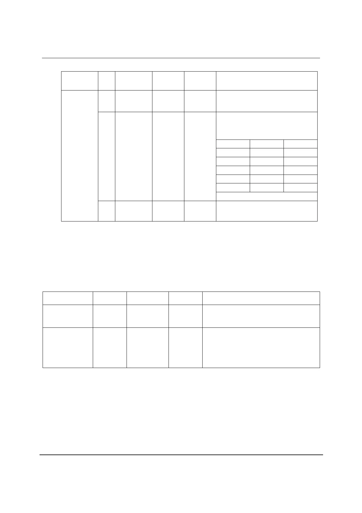
REGISTER
ADDRESS
BIT LABEL CHANNEL
STATUS
BIT
DEFAULT DESCRIPTION
0 MAXWL 32 1 Maximum Audio Sample Word Length
0 = 20 bits
1 = 24 bits
Audio Sample Word Length.
Used with MAXWL to indicate Tx word
length
000 = Word length not indicated
TXWL[2:0] MAXWL==1 MAXWL==0
001 20 bits 16 bits
010 22 bits 18 bits
100 23 bits 19 bits
101 24 bits 20 bits
110 21 bits 17 bits
3:1 TXWL[2:0] 35:33 101
All other combinations reserved
R22
SPDTX5
16h
7:4 ORGSAMP
[3:0]
39:36 0000 Original Sampling Frequency
Refer to S/PDIF specification (IEC 60958-3)
for full details.
Table 38 S/PDIF Transmitter Channel Status Bit Control Register 5
S/PDIF RECEIVER
The S/PDIF receiver has one input. This input can be configured as either single ended CMOS or as
a 500mVp-p comparator input, depending upon the state of the SPDIFINMODE register. The S/PDIF
receiver can be powered down if not in use by setting the SPDIFRXPD register bit. If the S/PDIF
receiver is powered down the system will wait until the end of the current S/PDIF frame before
powering down.
REGISTER
ADDRESS
BIT LABEL DEFAULT DESCRIPTION
R30
PWRDN
1Eh
1 SPDIFRXPD 1 S/PDIF Receiver Powerdown
0 = S/PDIF receiver enabled
1 = S/PDIF receiver disabled
R9
SPDMODE
09h
0 SPDIFINMODE 1 S/PDIF Input Mode Select
Selects the input circuit type for the receiver input.
0 = CMOS input
1 = Comparator input. Compatible with 500mVppAC
coupled consumer S/PDIF input signals. Refer to
S/PDIF specification (IEC 60958-3) for full details.
Table 39 S/PDIF Receiver Input Selection Registers